Download
1 / 1
10 likes | 122 Views
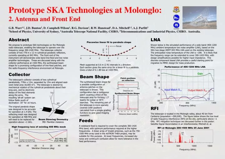
x focus. Synthesised Beam Shape. 45. Gain. 30. 15. |S| (dB). 0. Input Match S 11. Output Match S 22. -15. -30. 300. 1400. 850 Frequency (MHz). Prototype SKA Technologies at Molonglo: 2. Antenna and Front End

E N D
x focus Synthesised Beam Shape 45 Gain 30 15 |S| (dB) 0 Input Match S11 Output Match S22 -15 -30 300 1400 850 Frequency (MHz) Prototype SKA Technologies at Molonglo: 2. Antenna and Front End G.B. Warr1,2, J.D. Bunton3, D. Campbell-Wilson1, R.G. Davison1, R.W. Hunstead1, D.A. Mitchell1,2, A.J. Parfitt3 1School of Physics, University of Sydney, 2Australia Telescope National Facility, CSIRO, 3Telecommunications and Industrial Physics, CSIRO. Australia. Photo D. Bock Abstract We propose to prototype SKAtechnologies on the Molonglo radio telescope,enablingthe telescope to operate over the frequency range 300-1420 MHz. The telescope collector consistsof two 778m x 12m cylindrical parabolic reflectors, currently operating at 843 MHz. The front end of theinstrument will demonstrate wide band line-feed and low noise amplifiertechnologies. These are discussed along with the collector performance at1420 MHz, the synthesised beam shape for a promising configuration ofline-feed patches, and the radio-frequency interference environment at Molonglo. Collector The telescope’s collector consists of two cylindricalparaboloids, 778m x 12m, separated by 15m and aligned east-west (total area 18,000 m2). The telescope is steered by mechanical rotation of the cylindrical paraboloids about their LNA Shown below is the simulated performance of a wide band (400-1200 MHz) ambient temperature low noise amplifier (LNA), based on the 50W two-stage HEMT 843 MHz LNA used on the existing telescope. The anticipated noise temperature of the LNA is ~20K. It is likely that the frequency range can be extended to cover 300-1420 MHz, with design simplifications possible for higher input impedance. This discrete component based LNA provides a useful starting point for migration to MMIC design for mass production. Piecewise linear fit to parabola shape • Mesh supported at 0.6 m (2 ft) intervals in x direction. • Each section gives the same error for a linear fit to a parabola. • Gives a total of 0.1 dB loss at 1420 MHz. Performance of 400-1200 MHz LNA Beam Shape The synthesised beam shape for a possible configuration of antenna patches on the telescope is shown. This configuration has a contiguous patch covering a third of the telescope area for forming 1.3’ beams for pulsar or SETI searches. The remaining part of the telescope is more sparsely covered (with positions calculated from a simple grading function) to give good imaging resolution. Patch positions on reflectors -800 0 800 long axis, and by electronic delays of the feed elements along the arms. The resulting ‘alt-alt’ system can follow fields south of declination -30° for ±6 hours. The original parabola shape was designed to be accurate for operation at 1.4 GHz. The reflecting mesh was designed for operation at 408 MHz and will need to be replaced for operation above ~1 GHz. Distance (m) RFI The telescope is located in the Molonglo valley, about 40 km from Canberra (population ~300,000). The figure below shows the low level of radio frequency interference (RFI) at the site, particularly above ~1 GHz. RFI mitigation techniques are discussed further in the poster: Satellite Signal Decorrelation in an Interferometer, Mitchell et. al. Feeds A wideband feed is required to cover the complete 300-1420 MHz band, with optimum performance required at the higher frequencies. A linear array of Vivaldi antennas, such as the 750-1500 MHz array used in the ASTRON THEA project, may be suitable for this purpose. At lower frequencies, increased sky noise and continuum confusion allow for more tolerance in the feed performance. Beam Steering Geometry MD: Meridian Distance. High frequency loss of existing 408 MHz mesh RFI at Molonglo 200-1500 MHz 25 June 2001 UHF TV VHF TV GSM 843 MHz NS Original mesh designed for 408 MHz (1/2” NS x 1” EW) 1420 MHz NS