Download
1 / 22
220 likes | 226 Views
Lecture Objectives:. Introduce HW3 Learn about sorption chillers. Mixture 3. DPT SP. Set Point (SP). Mixture 2. Mixture 1. DBT SP. Sequence of operation (PRC research facility). Control logic: Mixture in zone 1 : IF (( TM<TSP) & (DPTM<DPTSP) ) heating and humidifying

E N D
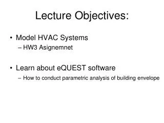
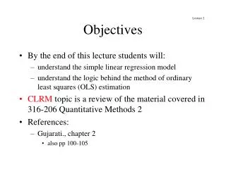
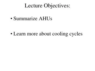
Lecture Objectives: • Introduce HW3 • Learn about sorption chillers
Mixture 3 DPTSP Set Point (SP) Mixture 2 Mixture 1 DBTSP Sequence of operation(PRC research facility) Control logic: Mixture in zone 1: IF (( TM<TSP) & (DPTM<DPTSP) ) heating and humidifying Heater control: IF (TSP>TSA) increase heating or IF (TSP<TSA) decrease heating Humidifier: IF (DPTSP>DPTSA) increase humidifying or IF (DPTSP<DPTSA) decrease humid. Mixture in zone 2: IF ((TM>TSP) & (DPTM<DPTSP) ) cooling and humidifying Cool. coil cont.: IF (TSP<TSA) increase cooling or IF (TSP>TSA) decrease cooling Humidifier: IF (DPTSP>DPTSA) increase humidifying or IF (DPTSP<DPTSA) decrease hum. Mixture in zone 3: IF ((DPTM>DPTSP) ) cooling/dehumidifying and reheatin Cool. coil cont.: IF (DPTSP>DPTSA) increase cooling or IF (DPTSP<DPTSA) decrease cooling Heater control: IF (TSP>TSA) increase heating or IF (TSP<TSA) decrease heating
HW3 • Writhe a sequence of operation instruction list for the air handling unit from HW2 (problems: 3&4)
HW3 • You will need to define: • what environmental variable/condition change - Temperature and RH of ambient air, Q cooling, Q heating, ….. • which variables can you control • recirculation rate, recirculation position, Total flow rate, TCC,… C) which variable will you control - ….. D) how are you going to “move” between different operation schemes E) writhe “if - else” set of instruction for different controlled devices while considering different operation scheme (see the example I gave you in class)
Absorption Cycle Replace compressor Same as vapor compression but NO COMPRESSOR
Absorption cooling cycle Relatively simple thermodynamics with addition of mixtures (water – ammonia) Rich solution of Heat H2O + NH3 H2O H2O Rich solution of H2O + NH3
Mixtures(T-x diagram) Dew point curve Saturated vapor Mixture of liquid and vapor Saturated liquid Bubble point curve For P= 4 bar
h-x diagram hfg for H2O hfg for NH3 Isotherms are showmen only in liquid region
Composition of h-x diagram Saturated vapor line at p1 Equilibrium construction line at p1 1e Used to determine isotherm line in mixing region! Start from x1; move up to equilibrium construction line; move right to saturated vapor line; determine 1’; connect 1 and 1’. Isotherm at P1 and T1 Adding energy B A x1 X1’ mass fraction of ammonia in saturated vapor
h-x diagramat the end of your textbook you will find these diagramsfor 1) NH3-H2O2) H2O-LiBr LiBr is one of the major liquid descants in air-conditioning systems
Adiabatic mixing in h-x diagram(Water – Ammonia) From the textbook (Thermal Environmental Eng.; Kuehen et al)
Absorption cooling cycle Rich solution of Heat H2O + NH3 H2O H2O Rich solution of H2O + NH3 Cooled env.
Mixing of two streams with heat rejection (Absorber) m2 =pure NH3 (x2=1) m3 mixture of H2O and NH3 m1 m3 m2 2 m1 Q cooling 3’ Mixture of 1 and 2 Heat rejection Mass and energy balance: (1) 1 3 (2) (3) x3 x From mixture equation: What happens if X2 ≠ 1 ? Substitute into (2) Substitute into (3) From adiabatic mixing (from previous slide)
Change of pressure(pump) Sub cooled liquid at p2 2 Saturated liquid at p1 1 p1 ≠p2 m1 =m2 p2 Saturated liquid at x1 =x2 2 p1 Saturated liquid at 1 x1=x2
Heat transfer with separation into liquid and vapor (Generator) Saturated vapor Heat =2V Sub cooled liquid Saturated liquid We can “break” this generator into 2 units heating m4 Q12 /m1 2L= m1 =m2 Separator mixture sub cooled liquid x1 m3 Q12 Apply mass and energy balance In the separator : What happens if 1 is not sub cooled liquid ? Apply mass and energy balance In the heat exchanger defines point 2 in graph Defines points 3 and 4 in graph
Heat rejection with transformation from vapor to liquid (Condenser) Saturated vapor at p1 m1 Saturated vapor 1 heat rejection m2 Q1-2/m1 m1 =m2 Saturated liquid at p1 x1 =x2 2 p1 =p2 x1=x2
Throttling process (Expansion valve) Saturated vapor 1 2V 1 2 T1 h1 =h2 2 p1 Saturated liquid at p1 ≠p2 T2 2L Saturated liquid p2 m1 =m2 At the end of expansion we get from X1=X2 liquid X2V vapor and X2L liquid Saturated liquid at p1 ≠p2 x1 =x2 x1 =x2 h1 =h2
Simple absorption system 3V 3L 3LLP
Simple absorption system Saturated vapor at p2=p3=p4 3V 6 3 5V mixing 1’ Needed thermal energy Useful cooling energy 4 3L 5 3LLP 2 Saturated liquid at p2=p3=p4 Saturated liquid at p1=p5=p6=p3_LLP 1 5L
Heat transfer with separation into liquid and vapor (Generator) How to move point 4 to right ? =2V =2V heating m4 Q12 /m1 2L= 2L= =m2 m1 =m2 mixture Separator mixture sub cooled liquid x1 x1 m3 Q12 m3 Q12
Heat rejection with separation into liquid and vapor (Enrichment NH3 in the vapor mixture) This is our point cooling 1 4=2V Separator 6=5V Q12 /m1 cooling Q45 /m4 x8 m8 8 7 5 m1 =m2 2 mixture isotherm sub cooled liquid m3 2L Q12 x8 x1