Download
1 / 7
70 likes | 239 Views
CCUM Tests and DCU Calibration. STATUS REPORT. Setup and Avaibility. Electrical FEC with PMC carrier. CCU/DCU test main board. 2D Barcode Scanner *. FLUKE189 multimeter + T° sensor **. TEC and TIB CCUs. * Pickup from PETAL test setup. ** TOB use IR Thermometer.

E N D
CCUM Tests and DCU Calibration STATUS REPORT
Setup and Avaibility • Electrical FEC with PMC carrier • CCU/DCU test main board • 2D Barcode Scanner* • FLUKE189 multimeter + T° sensor ** • TEC and TIB CCUs * Pickup from PETAL test setup ** TOB use IR Thermometer
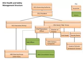
CCU test and DCU Calibration main board DCU reference CCU Board DCU (to calib) CCUM
~ 900 CCU-TEC ~ 700 CCU-TIB CCUs avaibility and report • not tested (to be @ Strbg) • ? • Tested @ CERN • Separated in 5 groups @ Strbg • CCU adresses defined (0x3F, 0x5F, 0x6F, 0x77, 0x7B)
CCUM TEC Identification : 2D Codebars • type description barre code • 04 CCU-TEC-F0 302 5200 04 00001 petals F in end cap n° 0 302 5200 04 00200 • 05 CCU-TEC-F1 302 5200 05 00201 petals F in end cap n° 1 302 5200 05 00400 • 06 CCU-TEC-B0 302 5200 06 00401 petals B in end cap n° 0 302 5200 06 00600 • 07 CCU-TEC-B1 302 5200 07 00601 petals B in end cap n° 1 302 5200 07 00800 • 08 CCU-TEC-DOM 302 5200 08 00801 CCU-TEC-DOM 302 5200 08 01000
DCU Calibration : Procedure for TEC/TIB ADC a. Apply Vref_j (J=1..4) to DCU Channel 2 or Channel 3 b. Read DCU Channel 2 or Channel 3 c. Evaluate Gain and Offset (Vin= G * ADCout + D) I20µA a. Read DCU_Channel 0 b. Evaluate I20µA I10µA a. Read DCU_Channel 1 b. Evaluate I10µA Temperature Sensor a. Read DCU_REF_channel 7 b. Read DCU_channel 7 TIME PROCESS ~ 10 min/ CCUM-DCU board
CCU and DCU in DATABASE XML file • Codebare • CCU Address • Tool_Id = 2403 • DCU_Id (_H, _M, _L) • Gain (G in µV/ADC) and Offset (D in µV) • I 20µA and I 10µA • Channel 7 (= DCU Sensor) both DCU • T° (external) both DCU • Offset (D in °C)