Download
1 / 79
790 likes | 796 Views
RTL Coding for FPGA. Speaker: Tsung-Yi Wu. Verilog. Verilog is a HARDWARE DESCRIPTION LANGUAGE (HDL). Verilog is first introduced in 1984 for Gateway Verilog-XL digital simulator

E N D
RTL Coding for FPGA Speaker: Tsung-Yi Wu
Verilog • Verilog is aHARDWARE DESCRIPTION LANGUAGE (HDL). • Verilog is first introduced in 1984 for Gateway Verilog-XL digital simulator • In 1989, Gateway acquired by Cadence. Then in 1990, Cadence release the Verilog language and Verilog PLI to public.
Verilog • Open Verilog International(OVI) was formed to maintain the Verilog standard, in 1993, OVI releases the Verilog 2.0 Reference Manual, then becomes the IEEE 1364-1995 (Verilog-1995)
Verilog • The specification of the Verilog-2001 standard is complete • Voting draft completed March 1st, 2000 • The official standard will be IEEE Std. 1364-2001
On-line Learning and Documents • http://www.sutherland-hdl.com/on-line_ref_guide/vlog_ref_top.html • http://toolbox.xilinx.com/docsan/2_1i/
Simulation and Synthesis • Simulation? • Synthesis? • Testing? • Verification? • P&R? • Configuration?
Get a Simulator and Synthesizer • http://www.xilinx.com/sxpresso/webpack.htm • Register Now • Register for ModelSim
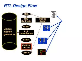
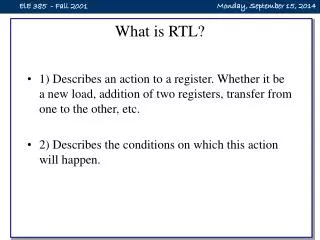
Register Transfer Level (RTL) • Any code that is synthesizable is called RTL code.
Gate Level • Within the logic level the characteristics of a system are described by logical links and their timing properties.
Introduction: Basic Verilog • Integer Literals Integer literals can have underscores embedded in them for improved readability. For example, • Binary literal 2’b1Z • Octal literal 2’o17 • Decimal literal 9 or ’d9 • Hexadecimal literal 3’h189 • Decimal literal 24_000
Introduction: Basic Verilog • 6'hCA 001010 truncated, not 11001010 • 6'hA 001010 filled with two '0' on left • 16'bZZ Z Z Z Z Z Z Z Z Z Z Z Z Z Z Z filled with 16 Z's
Introduction: Basic Verilog • Module Port Declarations input a,b; output sum; inout c; • An Example module adder(a,b,sum); input a,b; output sum; : endmodule
Introduction: Basic Verilog • Data Types real a, b, c; // a,b,c to be real integer j, k; // integer variable integer i[1:32]; // array of integer variables reg [8*14:1] string ; /* This defines a vector with range [msb_expr: lsb_expr] */ reg [15:0] mem16X512 [0:511]; // 16-bit by 512 word memory // mem16X512[4] addresses word 4 // the order lsb:msb or msb:lsb is not important wire net1;
Introduction: Basic Verilog • Net types • wire tri • wand triand • wor trior • tri0 tri1 • supply0 supply1 • trireg
Introduction: Basic Verilog • Relational Operators • a<b a less than b • a>b a greater than b • a<=b a less than or equal to b • a>=b a greater than or equal to b • Arithmetic Operators +, -, *, /, % (the modulus operator)
Introduction: Basic Verilog • Equality Operators • a === b a equal to b, including x and z • a !== b a not equal to b, including x and z • a == b a equal to b, resulting may be unknown • a != b a not equal to b, result may be unknown
Introduction: Basic Verilog • Logical Operators • ! logic negation • && logical and • || logical or
Introduction: Basic Verilog • 0 if the relation is false • 1 if the relation is true • x if any of the operands has unknown x bits • z ?
Introduction: Basic Verilog • Bitwise Operators • ~m Invert each bit of m • m&n AND each bit of m with each bit of n • m|n OR each bit of m with each bit of n • m^n Exclusive OR each bit of m with n • Exercise ~(4’b0011)=?
Introduction: Basic Verilog • Example • 0&x = 0 • 1&x = x&x = x • 1|x = 1 • 0|x = x|x = x • 0^x = x
Introduction: Basic Verilog • << left shift • >> right shift • {b, {3{c, d}}} this is equivalent to {b, c, d, c, d, c, d} • out = (enable) ? data : 8'bz; // Tri state buffer
Introduction: Basic Verilog module dff (q,qb,clk,d,rst); input clk,d,rst ; // input signals output q,qb ; // output definition wire dl,dbl ; // parameter value assignment paramter delay1 = 3, delay2 = delay1 + 1; nand #delay1 n1(cf,dl,cbf), n2(cbf,clk,cf,rst); nand #delay2 n3(dl,d,dbl,rst), n4(dbl,dl,clk,cbf), n5(q,cbf,qb), n6(qb,dbl,q,rst); endmodule
Introduction: Basic Verilog • initial : initial blocks execute only once at time zero (start execution at time zero). • always : always blocks loop to execute over and over again, in other words as name means, it executes always • initial is un-synthesizable statement
Introduction: Basic Verilog • Example : initial and always Initial always @ (posedge clk) beginbegin : D_FF reset = 0;if (reset == 1) q <= 0;q <= 0; end else q <=d; end
Introduction: Basic Verilog • Bug? wire clk, reset reg enable, data; Initial begin clk = 0; reset = 0; enable = 0; data = 0; end
Introduction: Basic Verilog • for (i = 0 ; i < 7 ; i=i+1) memory[i] = 0 ; // initialize to 0 • repeat (bit-width) b = b << 1; • case (select) 0: out[0] = 1; 1: out[1] = 1; endcase
Introduction: Basic Verilog • while(delay) begin @(posedge clk); ldlang = oldldlang; delay = delay - 1; end
Introduction: Basic Verilog • Structural model of AND gate from two NANDS module and_from_nand(A, B, Y);input A, B;output Y;wire W;// Two instantiations of the module NANDnand U1(A, B, W);nand U2(W, W, Y); endmodule
Introduction: Basic Verilog • always @ (posedge enable) repeat (20) @ (posedge clk) ; • while (mem_read == 1'b1) begin wait (data_ready) data = data_bus; read_ack = 1; end
Introduction: Basic Verilog • Function function [range] FCTID;{input [range] {ARGID,};}[{declaration}]begin [{sequential_statement}]endendfunction
Introduction: Basic Verilog • Task task TASKID;[{input | output | inout [range] {ARGID,};}][{declaration}]begin [{sequential_statement}]end
Introduction: Basic Verilog • System task • $stop Interrupt • $finish Terminate • $display[defbase]([fmtstr,] {expr,}); • $monitor[defbase] ([fmtstr,] {expr,}); • Compiler Directives • `define WORD_SIZE 32 • `include head.v • `timescale100 ns / 1 ns
Introduction: Basic Verilog • Example • $display( “Example of using function”); /* display to screen */ • $monitor($time, “a=%b, clk = %b, add=%h”,a,clk,add); // monitor signals • $setuphold( posedge clk, datain, setup, hold); // setup and hold checks
Combination CKT Coding • Combinational circuit is used to calculate the next state of the flip-flops • Data Path can be constructed by combination CKT
Combination CKT Coding • Verilog Example of Priority Encoded if Statement module mult_if(a, b, c, d, sel, z); input a, b, c, d; input [3:0] sel; output z; reg z; always @(a or b or c or d or sel) begin z = 0; if (sel[0]) z = a; if (sel[1]) z = b; if (sel[2]) z = c; if (sel[3]) z = d; end endmodule
Combination CKT Coding • Verilog Example for Single if Statement (Not Priority Encoded) module single_if(a, b, c, d, sel, z); input a, b, c, d; input [3:0] sel; output z; reg z; always @(a or b or c or d or sel) begin z = 0; if (sel[3]) z = d; else if (sel[2]) z = c; else if (sel[1]) z = b; else if(sel[0]) z = a; end endmodule
Combination CKT Coding • Verilog for Single case Statement module case1(a, b, c, d, sel, z); input a, b, c, d; input [3:0] sel; output z; reg z; always @(a or b or c or d or sel) begin casex (sel) 4’b1xxx: z = d; 4’bx1xx: z = c; 4’bxx1x: z = b; 4’bxxx1: z = a; default: z = 1’b0; endcase end endmodule
Combination CKT Coding • Example 3-1 Verilog for Decoder Using Indexing module decoder_index (in1, out1); parameter N = 8; parameter log2N = 3; input [log2N-1:0] in1; output [N-1:0] out1; reg [N-1:0] out1; always @(in1) begin out1 = 0; out1[in1] = 1’b1; end endmodule
Combination CKT Coding • Example 3-3 Verilog for Decoder Using Loop module decoder38_loop (in1, out1); parameter N = 8; parameter log2N = 3; input [log2N-1:0] in1; output [N-1:0] out1; reg [N-1:0] out1; integer i; always @(in1) begin for(i=0;i<N;i=i+1) out1[i] = (in1 == i); end endmodule
Combination CKT Coding • Example 3-8 Verilog for Reduction XOR Chain module XOR_reduce (data_in, data_out); parameter N = 5; input [N-1:0] data_in; output data_out; reg data_out; function XOR_reduce_func; input [N-1:0] data; integer I; begin XOR_reduce_func = 0; for (I = N-1; I >= 0; I=I-1) XOR_reduce_func = XOR_reduce_func ^ data[I]; end endfunction always @(data_in) begin data_out <= XOR_reduce_func(data_in); end endmodule
Combination CKT Coding • Verilog for XOR Tree module XOR_tree(data_in, data_out); parameter N = 5; parameter logN = 3; input[N-1:0] data_in; output data_out; reg data_out; function even; input [31:0] num; begin even = ~num[0]; end endfunction
Combination CKT Coding begin for (I=NUM-1; I>=1; I=I-2) begin result[J] = temp[I] ^ temp[I-1]; J = J-1; end result[0] = temp[0]; end temp[N-1:0] = result[N-1:0]; NUM = (NUM+1)/2; end XOR_tree_func = result[0]; end endfunction always @(data_in) begin data_out <= XOR_tree_func(data_in); end endmodule • Verilog for XOR Tree function XOR_tree_func; input [N-1:0] data; integer I, J, K, NUM; reg [N-1:0] temp, result; begin temp[N-1:0] = data_in[N-1:0]; NUM = N; for (K=logN-1; K>=0; K=K-1) begin J = (NUM+1)/2; J = J-1; if (even(NUM)) for (I=NUM-1; I>=0; I=I-2) begin result[J] = temp[I] ^ temp[I-1]; J = J-1; end else
Combination CKT Coding • Example 4-1 Original Verilog Before Logic Duplication module BEFORE (ADDRESS, PTR1, PTR2, B, CONTROL, COUNT); input [7:0] PTR1,PTR2; input [15:0] ADDRESS, B; input CONTROL; // CONTROL is late arriving output [15:0] COUNT; parameter [7:0] BASE = 8’b10000000; wire [7:0] PTR, OFFSET; wire [15:0] ADDR; assign PTR = (CONTROL == 1’b1) ? PTR1 : PTR2; assign OFFSET = BASE - PTR; //Could be any function // f(BASE,PTR) assign ADDR = ADDRESS - {8’h00, OFFSET}; assign COUNT = ADDR + B; endmodule