Download
1 / 15
150 likes | 155 Views
Dynamic Frequency Scaling using on-chip Thermal Sensors in ASAP7 7nm Predictive PDK. Vaibhav Verma Mandi Das Wole Jaiyeoba. Motivation. We wanted to build an on-chip thermal sensing unit. And we wanted to scale voltage and frequency of the processor based on thermal sensor data.

E N D
Dynamic Frequency Scaling using on-chip Thermal Sensors in ASAP7 7nm Predictive PDK Vaibhav Verma Mandi Das Wole Jaiyeoba
Motivation • We wanted to build an on-chip thermal sensing unit. • And we wanted to scale voltage and frequency of the processor based on thermal sensor data. We will build a beautiful DVFS unit Well voltage scaling isn’t our cup of tea
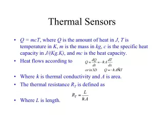
Thermal Sensor (TS) Temperature Dependent Delay Temperature Independent Delay Clock IN Temperature Dependent Pulse Width Based on Chen et al., “A Time-to-Digital-Converter-Based CMOS Smart Temperature Sensor”, IEEE Journal Of Solid-State Circuits, Vol. 40, No. 8, August 2005
Why temperature Independent Delay? • Well why not? • Essentially we could have just used wire delay to get the desired temperature dependent pulse width. • But that leads to huge “minimum pulse” for lower range of temperatures. • Hence we designed temperature (mostly) invariant delay line to offset the pulse width for better accuracy. • And anyway what’s VLSI project without a li’l circuit design!!
Schematics – Temperature Sensor Temperature Invariant Delay element Temperature Sensor
Performance of TS across temperature Mostly linear output across temperature range (-40°C to 125 °C) 60.9 ps 64.3 ps 2.3 ps
Time to Digital Converter (TDC) • The output of thermal sensor is a pulse width varying with temperature. • We need TDC to convert this analog information to digital output. • This digital output is then used to control frequency scaling.
Schematics – Time to Digital Converter D-Flip Flop
Dynamic Frequency Scalar (DFS) Why do we need it?? The DFS (Dynamic Frequency Scalar) collects digitalized data from the Time to Digital Converter (DTC) and scales the frequency of the master clock accordingly. This output clock becomes the new clock which drives the chip.
Dynamic Frequency Scalar Features: Final system output clock • **Glitch free** (via use of the two synchronizing flip-flops) • Easily scalable to larger frequency variations. Based on Browne B. Richard et al., “Low-Latency, HDL-Synthesizable Dynamic Clock Frequency Controller with Self-Referenced Hybrid Clocking”, Circuits and Systems Conference (2006) Glitch-free dynamic frequency controller.
Dynamic Frequency Scalar: Schematic Fig: DFS Schematic from ASAP7 PDK Cadence System clock DFFs: clock dividers DFFs: clock synchronizers MUX: clock select Fig: schematic of the Digital Frequency Scalar
DFS – Simulation Waveform Diagram Fig: simulation of the DFS schematic
Difficulties encountered during design and simulation • The hardest part of the project was to tune the delays in TDC to match the range of pulse widths for different temperatures. • Also, using relative ground, we got unexpected results from simulating the design schematic. However, when we connected Vss and Vpw to absolute ground, we got the correct, required behavior. • We also faced hspice DC convergence issues in many of our final runs.