Download
1 / 24
240 likes | 403 Views
Beam Tracking Detectors. For charged particles Transmission detectors Event by event (≠ monitoring). Why measure the ion trajectory ? Information about the reaction process angular distributions, velocity Identification of the particle

E N D
Beam Tracking Detectors • For charged particles • Transmission detectors • Event by event (≠ monitoring)
Whymeasure the ion trajectory ? Information about the reactionprocess angular distributions, velocity Identification of the particle curvature radius in a magneticfieldgivesmomentum unknown distribution With a perfect beam track only the outgoing particles Incoming beam v0 (x0,y0) θ0 perfect beam θ1 θ1 Incident angle Position of vertex Velocity Scattering angle Target What? Determine the trajectories of ions before the interaction point positions + time of flight Need a transmission detector, with position and time measurement on an event by event basis
Ion-matter interaction (Mainly electromagnetic) enough to detect the ion BUT not too much, not to perturb its trajectory active layer ion after θf =θi +θ Ei = Ei - ΔE + E Qf = Qi+ Q ion before (θi , Ei,Qi) dead layer can be calculated and corrected in the active layer gives the detection signal Energy losses ΔE Energy straggling E Angular straggling θ Charge exchange Q Stochastic processes error on measurement Stochastic process charge state distribution for Ei< 50MeV/u
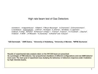
Losses, Straggling and Detection Set-up 40Ca Slowed down BEAM and tracking activity at GSI by Plamen Boutachkov e.g. HISPEC/DESPEC @ GSI : 3 to 150 A.MeV
Relativistic regime : 500MeV/u Diamond tracking for R3B @ FAIR (2013+) Sources: R.Gernhäuser (TU-München) The super FRS will provide heavy ions with ~700MeV/u Measurement of all kinematic variables in a HI reaction Different tasks: High resolution tracking in the super FRS, radiation hard (SFRS) 106 cm-1 s-1 2 x TOF (SFRS – target) (reaction products)
Diamond as a detector material low capacitance low noise good heat conductivity ( 5 x higher than Cu ) large band gap of 5.5 eV small signal (< half of a Si of similar size) high charge carrier velocity saturation fast pulse response time Diamond Crystal production chemical vapour deposition (CVD) commercial production polycrystalline diamonds (PCD) thickness 50-500µm max size ~ 5x5cm2 price ? (100 euro/det.) single crystal diamond (SCD) smaller (max 25x25 mm2) better performance (energy resolution) more expensive (5xPCD) Short characteristics of CVD diamond detectors Cr-Au foil ~0.1mm • Diamond detectors performance • very fast timing • pulse risetime: 200 ps • width: 2ns (PCD) 5ns (SCD) • operating voltage 1 V/mm • radiation hardness • -Tests with 2x10¹⁵ p/cm2 did not show any significant deterioration of a sig./noise • -pumping effect (PCD) : improvement with increasing dose • position resolution • below 10mm can be achieved with strip detectors X and Y • efficiency • 70%PCD-100% SCD • Diamonds as TOF detectors • tests with 1GeV/u U beam resulted in TOF of s=20 ps Source: M. Gorska (GSI)
Virtues & Flaws of diamond detectors - Radiation hard (>2.15p/cm2) - low occupation time high counting rate 107pps - ultra fast signal time resolution σ = 30ps - reasonableenergyresolutionσ = 17keV (single crystal) - small size, biggest in use 60x40mm2 [PCD, Cave A @ GSI] - thickness > 50µm restricted to high energy - require high speed electronics - single crystals have better performances but are smaller (few mm2) Mosaic detector ? very promising technique, lot of developments
Relativistic regime : 500MeV/u KaBes on the NA48 exp @ CERN (in use) The micromegas TPC B. Peynaud, NIM A 535 (2004) 427 Study of CP violation by the simultaneous detection of K+ and K- Need to measure trajectories to obtain the momentum of individual Kaons (~60GeV/c)
Time projection Chamber with Micromegas Drift (-HT 2) Drift Region h=6cm ve- = 8cm/µs Drift time = Y position Gaz (Here: Ne(79%)+C2H6(11%)+CF4(10%) ) the electrons have a constant velocity in the drift zone i+ E ~ 900V/cm e- ionization point Mesh (-HT 1) Amplification gap < 100 mm E ~ 50 kV/cm strips charge readout A fast avalanche occurs in the short gap fast electron signal no signal from the drifting ions because of the shielding mesh Each strip gives an independent time signal high counting rate 2 orthogonal detectors required to have X and Y
KaBes drift chambers for real • Performances • Time resolution = 0.7 ns () • Spatial res. of 70 m • 40 MHz, expected up to 1GHz • Efficiency close to 100 % Drift field Amplification region
Virtues & Flaws of Micromegas TPC • • - Radiation hard • - Very high counting rate : up to 109pps ! • Very good position resolution < 100µm • Bulk micromegas : robust and easy to build • • - 1 direction only • - Moderate energy resolution (~10%) • - Need an independent time signal for trigger Micromegas Technology by Thomas Papavangelou Micromegas gas detectors have a wide range of applications since the “drift zone” can include a converter that produce electrons from any kind of initial radiation e.g. piccolo micromegas for neutron detection J. Pancin & al. NIMA 592 (2008) 104
Relativistic muons GEMs in the COMPASS experiment @ CERN Gas Electron Multipliers 140µm 70µm Copper Kapton 50µm Copper Ar + CO2 mixture Readout X and Y
Virtues & Flaws of GEM • • Radiation hard • Large size (>1m2) • - Very high counting rate : 105Hz/mm2 • - Excellent position resolution σ ~ 40µm • • Moderate gain (~30-50) but several stages can be added • Dead zones due to spacers • Poor energy resolution (~27%) • High capacitance strong discharges Gas Electron Multiplers by Serge duarte Pinto Spherical GEM for parallax correction !
Intermediate energy : 50MeV/u CATS detectors at GANIL, Caen (in use) In Beam low pressure MWPC Beam Tracking Detectors proton target (polypropylene) Fragmentation 12C10,11C+… recoiling p Target point 11C identification with a spectrometer
BEAM 2nd tracking detector Target 7cm
Effect of trajectory reconstruction 11C+p 11C+p’ 40.6 MeV/u C. JOUANNE (SPHN) PHD 2002 11C 11C E* Θp Proton Ep LOW Pressure Gas detectors by Julien Pancin Without Beam Tracking reconstructed on target With Beam Tracking 1.5m upstream 0.5m upstream Large Beam emittance ~10π mm.mrad (hor+vert)
Virtues & Flaws of in-beam low pressure MWPC - fast signal good time resolution σ = 100ps - good position resolutionσ = 100µm - highdetectionefficiency (~100%) - large size available (>100cm2) - cheap and canberepaired - Thin : ~5µm of Mylar (fromwindows and cathodes) - vulnerable to discharge : rate ~ 105pps - 1.5µm windows required Eion > 10MeV/u - fragile and delicate to use
Very low Energy regime : 5MeV/u e.g.: SPIRAL/SPIRAL2 radioactive beams (in use / 2014) Tracking at Focal plane Target point Beam
Secondary electrons Emissive foil Detectors Very low thickness < 1µm foil Emissive foil (Mylar+Al, Carbon) Ions B E Secondary emission - low energy electrons (few eV) - depends on the material (CsI…) - surface process - proportional to dE/dx • Electron detector : • Micro-channel plate • Gaseous detector • Scintillator • …
Micro Channel Plates ϕ=10-40µm <10cm 0.4-3mm thickness Borosilicate MCP developments 20x20cm2 ! - Superposition of resistive and photo-emissive (Al2O3) atomic layers - Similar gain as standard MCP Micro Channel plates by Michael Pfeiffer - Fast signals paired MCP - Poor uniformity (±10%) single MCP 2ns O.H.W. Siegmund & al. NIMA 639 (2011) 165
Low Pressure Gas Detector LOW Pressure Gas detectors by Julien Pancin Focal plane size : 10 x 40 cm2 A. Drouart & al, NIM A579, ( 2007) p1090
Virtues & Flaws of Emissive foil detectors • • - Detector as thin as it can be ( down to 20µg/cm2) • - Fast signal good time resolution σ < 100ps • • Poor sensitivity to high energy, light ions • Moderate position resolution σ~600µm • Require high electric field and/or magnetic field • Characteristics depend on the secondary electron detector • - gas detector : large size • - micro channel plate : high counting rate • - scintillating plastic : easy to use
Conclusions Beam tracking requires low thickness not to perturb the incoming ion good position and time resolution cope with high flux of particles
Thank you for your Attention • Enjoy the next talks !