Download
1 / 31
590 likes | 1.28k Views
Internal Combustion Engines. Applied Thermodynamics & Heat Engines. MOAZ HASSAN (Lecturer) Mechanical Engineering Department University of Lahore. Applied Thermodynamics & Heat Engines. Heat Engines.

E N D
Internal Combustion Engines Applied Thermodynamics & Heat Engines MOAZ HASSAN (Lecturer) Mechanical Engineering Department University of Lahore Applied Thermodynamics & Heat Engines
Heat Engines Any type of engine or machine which derives Heat Energy from the combustion of the fuel or any other source and converts this energy into Mechanical Work is known as a Heat Engine. Classification : 1. External Combustion Engine (E. C. Engine) : Combustion of fuel takes place outside the cylinder. Gas Turbine Steam Engine, etc. e.g. Steam Turbine,
Heat Engines 2. Internal Combustion Engine (I.C. Engine) : Combustion of fuel occurs inside the cylinder. e.g. Automobiles, Marine, etc.
Classification of I. C. Engines • Cycle of Operation : 1. Two – Stroke Engine. 2. Four – Stroke Engine • Cycle of Combustion : 1. Otto Cycle (Combustion at Constant Volume). 2. Diesel Cycle (Combustion at Constant Pressure). 3. Dual Cycle (Combustion partly at Constant Volume + Constant Pressure).
Classification of I. C. Engines • Arrangement of Cylinder : 2. Vertical Engine 1. Horizontal Engine. 3. V – type Engine 4. Radial Engine
Classification of I. C. Engines • Uses : 2. Marine Engine 1. Automobile Engine. 3. Stationary Engine 4. Portable Engine
Classification of I. C. Engines • Fuel used : • 1. Diesel Engine (CI) 2. Petrol Engine (SI) • 3. Gas Engine 4. Kerosene Engine • Speed of Engine : • 1. High Speed 2. Low Speed • Method of Cooling : • 1. Air – Cooled Engine. 2. Water – Cooled Engine
Classification of I. C. Engines • Method of Ignition : 1. Spark – Ignition (S.I.) Engine. 2. Compression – Ignition (C.I.) Engine
Classification of I. C. Engines • No. of cylinders : 1. Single Cylinder Engine. 2. Multi - Cylinder Engine
Application of I. C. Engines Road vehicles. Locomotives. APPLICATIONS Generators for Hospitals, Cinema Hall, and Public Places. Construction Equipments Pumping Sets
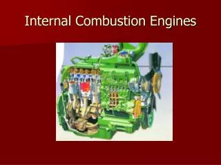
Construction • The engine comprises a cylinder block in which a cylinder is bored to accommodate the piston and Piston Rings. • It can be SI (Petrol) or CI (Diesel) Engine. • A crankshaft is mounted on one side of the cylinder block which is closed in an Oil pan/Sump. • The included space is called the Crankcase. • The oil pan contains a specified quantity of engine Lubricating oil. • The piston is connected to the Crankshaft by a connecting rod and a Gudgeon pin.
Construction • Space above the piston on the other side of the cylinder, is a Cylinder Head. • The free volume in the cylinder when the piston is at the extreme top in the cylinder is called the Combustion Chamber. • The cylinder head contains the Intake and Exhaust valves. • A valve mechanism opens and closes the valves. • This valve mechanism is activated by the Camshaft which is driven by the crankshaft at half-crankshaft speed. • An intake manifold with a Carburettor(in case of Petrol Engine-SI Engine) is connected to the intake port which leads to the intake valve and hence the cylinder, while the exhaust manifold is connected to the exhaust port.
Construction • Top Dead Centre (T.D.C) – when the piston is at the end of the upward stroke, that is the highest point which the piston can reach in the cylinder • Bottom dead centre (B.D.C) – when the piston is at the end of the downward stroke, that is the lowest point which the piston can reach in the cylinder • Stroke – the maximum distance of piston movement between extreme points; these extreme points are (T.D.C) and (B.D.C) and the crankshaft turns through 180° • Cycle – the four strokes of the piston; one cycle is completed during two crankshaft revolutions (720°)and one camshaft revolution.
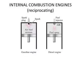
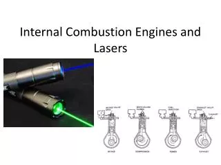
Operation - The Intake Stroke • The piston moves from t.d.c. toward b.d.c. • When the piston descends from t.d.c., the intake valve starts opening. • With the exhaust valve closed during the stroke, a partial vacuum or depression is created in the cylinder above the piston. • Atmospheric pressure fills this partial vacuum and, in doing so, passes through the carburettor barrel. • In the carburettor barrel petrol is mixed with air. • This air-fuel mixture fills the cylinder via the intake manifold and past the open intake valve. • Just after the piston reaches b.d.c., the intake valve is closed.
The Compression Stroke • Both the intake valve and the exhaust valve remain closed during this stroke and the piston moves from b.d.c. to t.d.c. • The petrol mixture is compressed in the relatively small combustion chamber. • Just before the piston reaches t.d.c., a high tension spark is introduced into the combustion chamber by means of the sparkplug and the petrol mixture is ignited.
The Power Stroke • Both valves still remain closed and as a result of ignition, combustion of the petrol mixture takes place rapidly. • High temperatures are developed as a result of this combustion and cause the gases to expand. • This expansion exerts considerable pressure on the piston and the force is transmitted to the crankshaft via the connecting rod, thereby giving a rotary motion (rotation) to the crankshaft.
The Exhaust Stroke • As the piston reaches b.d.c., the exhaust valve is opened. • The crankshaft rotates as a result of momentum in the crankshaft, assisted by the flywheel, and the piston moves from b.d.c. to t.d.c. • The piston forces out the burnt gases past the open exhaust valve to the exhaust manifold from where it is fed to the atmosphere by pipes. • When the piston reaches t.d.c., the engine is ready to start the following intake stroke and cycle.
ENVIRONMENT • A running engine emits the exhaust gas, carbon monoxide. • The gas is very harmful to both people and the environment. • So, Catalytic converters that convert the carbon monoxide to less harmful carbon dioxide. • Note : It operates on Otto Cycle.
Four – Stroke / Compressed Ignition Engine • It is similar to the petrol engine, except that : • It operates on Diesel Cycle. • The compression ratio is approximately 20:1 compared to a petrol engine which has a compression ratio of about 10:1. • On the compression stroke the fuel is injected and mixes with the compressed air a few degrees before the piston reaches t.d.c. • The mixture is ignited by the high temperature that results from the higher pressure of the compressed air/fuel on the compression stroke. i.e. No Carburetor.
Construction • However, the three-port two-stroke engine does not have valves. • Instead there are the intake port, the exhaust port and the transfer port, all of which are closed and opened by the moving piston. • A second important feature is the crankcase which is air-tight and which contains no lubricating oil as the oil is added to the petrol. • A third feature is the piston crown; its design promotes scavenging of the cylinder. (Scavenging occurs when the new gases from the bypass port push the burnt gases out the outlet port and so clean the cylinder.)
The Intake and Compression strokes • With the piston at b.d.c., the intake port is closed and the other two ports open. • At this stage, the cylinder above the piston is filled with the Air-petrol mixture. • During ‘piston-travel’ from b.d.c. to t.d.c., the transfer port is first closed by the piston and then the exhaust port. • As the piston ascends, the petrol mixture is compressed in the combustion chamber while a vacuum is created in the crankcase. • With the upward movement of the piston, the intake port is opened and the petrol mixture fills the vacuum in the crankcase. • Just before the piston reaches t.d.c., the compressed petrol mixture is ignited by a high tension spark.
The Power and Exhaust Strokes • After ignition of the petrol mixture, combustion causes high temperatures to develop, and as a result the gases expand. • These expanding gases force the piston towards b.d.c. and a powerful rotational movement is given to the crankshaft. • As the piston moves towards b.d.c., the intake port is closed and the petrol mixture is compressed in the crankcase. • With the further movement of the piston, the exhaust port is opened first and the burnt gases start escaping. • Just after this the transfer port is opened and the compressed petrol mixture in the crankcase enters the cylinder under pressure and assists in driving out the burnt gases.
Two – Stroke / Compression Ignition (C.I.) Engine • Its is Similar to two Stroke Engine (SI) except; • Fuel enters first then Air enter to burn the fuel like 4-Stroke CI Engine • No Carburetor.
Thank You ! Applied Thermodynamics & Heat Engines