Download
1 / 26
280 likes | 757 Views
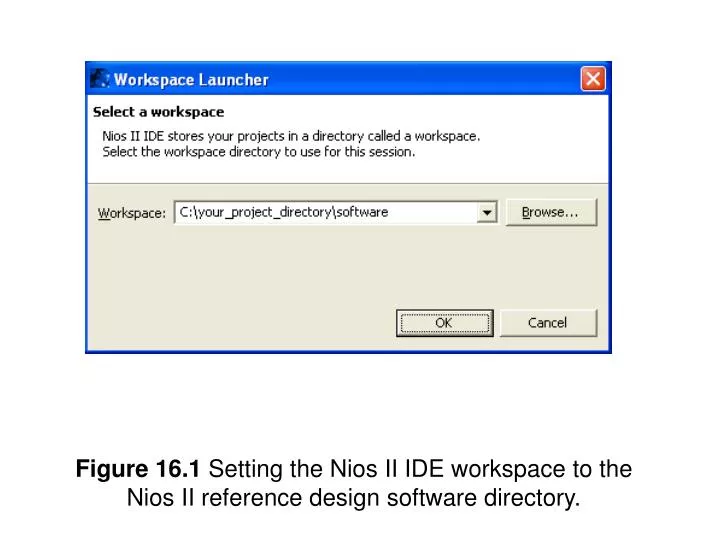
Figure 16.1 Setting the Nios II IDE workspace to the Nios II reference design software directory. Figure 16.2 Create a blank project for the Nios II reference design. Figure 16.3 These are the system library settings that should be used for this tutorial.

E N D
Figure 16.1 Setting the Nios II IDE workspace to the Nios II reference design software directory.
Figure 16.2 Create a blank project for the Nios II reference design.
Figure 16.3 These are the system library settings that should be used for this tutorial.
Figure 16.4 This is the C code necessary for providing a one second delay by directly accessing the system timer’s registers. The timer peripheral in this system is called timer0. #include “system.h” #include “altera_avalon_timer_regs.h” int main( void ) { IOWR_ALTERA_AVALON_TIMER_PERIODL( TIMER0_BASE, (48000000 & 0xFFFF) ); IOWR_ALTERA_AVALON_TIMER_PERIODH( TIMER0_BASE, ((48000000>>16) & 0xFFFF) ); IOWR_ALTERA_AVALON_TIMER_STATUS( TIMER0_BASE, 0 ); IOWR_ALTERA_AVALON_TIMER_CONTROL( TIMER0_BASE, 0x4 ); while( (IORD_ALTERA_AVALON_TIMER_STATUS( TIMER0_BASE ) & ALTERA_AVALON_TIMER_STATUS_TO_MSK) == 0 ) {} }
#include <sys/alt_alarm.h> int main( void ) { int first_val, second_val; second_val = 0; first_val = alt_nticks(); while( (second_val – first_val) < 1000000 ) { second_val = alt_nticks(); } } Figure 16.5 This is the C code necessary for providing a one second delay by using the HAL interface functions.
#include <unistd.h> int main( void ) { usleep( 1000000 ); } Figure 16.6 This is the C code necessary for providing a one second delay by using the standard ANSI C library functions
#ifndef _RPDS_SOFTWARE_H_ #define _RPDS_SOFTWARE_H_ #include <stdio.h> #include <unistd.h> #include "system.h" #include "altera_avalon_pio_regs.h" #endif //_RPDS_SOFTWARE_H_ Figure 16.7 This is your first C program’s main header file.
#include “rpds_software.h” int main( void ) { unsigned char led_val = 1; /* Print message to the Nios II IDE console via UART */ printf( "Hello World\n" ); while(1) { /* Output a 4-bit value to the LEDs */ IOWR_ALTERA_AVALON_PIO_DATA( LEDS_BASE, (led_val & 0xF) ); if( led_val == 8 ) led_val = 1; else led_val = led_val << 1; /* Wait for 0.5 seconds */ usleep( 500000 ); } return(0); } Figure 16.8 This is your first C program’s main source file.
Figure 16.9 Keep this dialog box open as long as the FPGA is being used.
Figure 16.10 Since this project uses the same Nios II processor as your first program, the same system library can be used. Select the rpds_software_syslib from the list of available libraries.
#ifndef _RPDS_UP3_TEST_H_ #define _RPDS_UP3_TEST_H_ #include <stdio.h> #include <unistd.h> #include "system.h" #include "alt_types.h" #include "sys/alt_irq.h" #include "sys/alt_flash.h" #include "altera_avalon_pio_regs.h" #endif //_RPDS_UP3_TEST_H_ Figure 16.11 This is the beginning of your C program’s main header file.
Table 16.1 Pushbutton to Device Mapping for Sample C Program
#include “rpds_up3_test.h” int main( void ) { volatile int function = 0; int ret_val; while(1) { switch( function ) { case 0x1: /* Test the LCD display */ ret_val = test_lcd(); break; case 0x2: /* Test the SRAM */ ret_val = test_sram(); break; case 0x4: /* Test the Flash memory */ ret_val = test_flash(); break; case 0x8: /* Test the SDRAM */ ret_val = test_sdram(); break; default: /* Do nothing */ break; } function = 0; usleep( 50000 ); /* Wait 50 ms */ } return(0); } Figure 16.12 This is the beginning of your C program’s main source file.
static void buttons_isr( void* context, alt_u32 id ) { volatile int *function = (volatile int*) context; *function = IORD_ALTERA_AVALON_PIO_EDGE_CAP( BUTTONS_BASE ); IOWR_ALTERA_AVALON_PIO_EDGE_CAP( BUTTONS_BASE, 0 ); IOWR_ALTERA_AVALON_PIO_IRQ_MASK( BUTTONS_BASE, 0xF ); } Figure 16.13 This is the interrupt service routine for the pushbuttons.
void lcd_init( void ) { /* Set Function Code Four Times -- 8-bit, 2 line, 5x7 mode */ IOWR( LCD_BASE, LCD_WR_COMMAND_REG, 0x38 ); usleep(4100); /* Wait 4.1 ms */ IOWR( LCD_BASE, LCD_WR_COMMAND_REG, 0x38 ); usleep(100); /* Wait 100 us */ IOWR( LCD_BASE, LCD_WR_COMMAND_REG, 0x38 ); usleep(5000); /* Wait 5.0 ms */ IOWR( LCD_BASE, LCD_WR_COMMAND_REG, 0x38 ); usleep(100); /* Set Display to OFF */ IOWR( LCD_BASE, LCD_WR_COMMAND_REG, 0x08 ); usleep(100); /* Set Display to ON */ IOWR( LCD_BASE, LCD_WR_COMMAND_REG, 0x0C ); usleep(100); /* Set Entry Mode -- Cursor increment, display doesn't shift */ IOWR( LCD_BASE, LCD_WR_COMMAND_REG, 0x06 ); usleep(100); /* Set the cursor to the home position */ IOWR( LCD_BASE, LCD_WR_COMMAND_REG, 0x02 ); usleep(2000); /* Clear the display */ IOWR( LCD_BASE, LCD_WR_COMMAND_REG, 0x01 ); usleep(2000); } Figure 16.14 This is the LCD initialization function.
alt_u32 test_lcd( void ) { int i; char message[17] = "Counting... "; char done[12] = "Done! "; /* Write a simple message on the first line. */ for( i = 0; i < 16; i++ ) { IOWR( LCD_BASE, LCD_WR_DATA_REG, message[i] ); usleep(100); } /* Count along the bottom row */ /* Set Address */ IOWR( LCD_BASE, LCD_WR_COMMAND_REG, 0xC0 ); usleep(1000); /* Display Count */ for( i = 0; i < 10; i++ ) { IOWR( LCD_BASE, LCD_WR_DATA_REG, (char)(i+0x30) ); usleep(500000); /* Wait 0.5 sec. */ } /* Write "Done!" message on first line. */ /* Set Address */ IOWR( LCD_BASE, LCD_WR_COMMAND_REG, 0x80 ); usleep(1000); /* Write data */ for( i = 0; i < 11; i++ ) { IOWR( LCD_BASE, LCD_WR_DATA_REG, done[i] ); usleep(100); } return(0); } Figure 16.15 This is the code to test the LCD display.
int main( void ) { volatile int function = 0; alt_u32 switches, ret_val; printf("Welcome to the Nios II Test Program\n" ); alt_irq_register(BUTTONS_IRQ, (void *) &function, buttons_isr); IOWR_ALTERA_AVALON_PIO_IRQ_MASK( BUTTONS_BASE, 0xF ); while(1) { switch( function ) { case 0x1: /* Test the LCD display */ printf("Testing LCD Display\n" ); lcd_init(); ret_val = test_lcd(); printf("...Completed.\n" ); break; case 0x2: /* Test the SRAM */ printf("Testing SRAM\n" ); ret_val = test_sram(); printf("...Completed with %d Errors.\n", ret_val ); break; case 0x4: /* Test the Flash memory */ printf("Testing Flash memory\n" ); ret_val = test_flash(); printf("...Completed with %d Errors.\n", ret_val ); break; case 0x8: /* Test the SDRAM */ printf("Testing SDRAM\n" ); ret_val = test_sdram(); printf("...Completed with %d Errors.\n", ret_val ); break; default: /* Do nothing */ break; } function = 0; switches = IORD_ALTERA_AVALON_PIO_DATA( SWITCHES_BASE ); IOWR_ALTERA_AVALON_PIO_DATA( LEDS_BASE, switches ); usleep( 50000 ); } return(0); } Figure 16.16 This is the completed main function.
alt_u32 test_sram( void ) { alt_u32 i, val; alt_u32 errors = 0; alt_u32 buffer[SRAM_MAX_WORDS]; /* Write data to SRAM */ for( i = 0; i < SRAM_MAX_WORDS; i++ ) { buffer[i] = i + 1000; } /* Check output from SRAM */ for( i = 0; i < SRAM_MAX_WORDS; i++ ) { if( buffer[i] != (i+1000) ) errors++; } return( errors ); } Figure 16.17 This is the code to test the SRAM memory device.
alt_u32 test_flash( void ) { alt_u32 i, errors = 0; alt_u32 in_buff[FLASH_MAX_WORDS], out_buff[FLASH_MAX_WORDS]; alt_flash_fd* flash_handle; flash_handle = alt_flash_open_dev( FLASH_NAME ); /* Create data buffer to write to Flash memory */ for( i = 0; i < FLASH_MAX_WORDS; i++ ) { in_buff[i] = i + 1000000; } /* Write data to Flash memory */ alt_write_flash( flash_handle, 0, in_buff, FLASH_MAX_WORDS*4 ); /* Read data from Flash memory */ alt_read_flash( flash_handle, 0, out_buff, FLASH_MAX_WORDS*4 ); /* Check output from Flash memory */ for( i = 0; i < FLASH_MAX_WORDS; i++ ) { if( out_buff[i] != (i+1000000) ) errors++; } alt_flash_close_dev( flash_handle ); return( errors ); } Figure 16.18 This is the code to test the Flash memory device.
alt_u32 test_sdram( void ) { alt_u32 i; alt_u32 errors = 0; alt_u32 *buffer = (alt_u32 *)SDRAM_BASE; /* Write data to SDRAM */ for( i = 0; i < SDRAM_MAX_WORDS; i++ ) { buffer[i] = (i + 1000000); } /* Check output from SDRAM */ for( i = 0; i < SDRAM_MAX_WORDS; i++ ) { if( buffer[i] != (i+1000000) ) errors++; } return( errors );} Figure 16.19 This is the code to test the SDRAM memory device.
#ifndef _RPDS_UP3_TEST_H_ #define _RPDS_UP3_TEST_H_ #include <stdio.h> #include <unistd.h> #include "system.h" #include "alt_types.h" #include "sys/alt_irq.h" #include "sys/alt_flash.h" #include "altera_avalon_pio_regs.h" /* LCD constants */ #define LCD_WR_COMMAND_REG 0 #define LCD_WR_DATA_REG 2 /* Memory constants */ #define SRAM_MAX_WORDS 8000 #define FLASH_MAX_WORDS 1000 #define SDRAM_MAX_WORDS 1000000 #endif //_RPDS_UP3_TEST_H_ Figure 16.20 This is the final copy of the rpds_up3_test.h header file.
#include "rpds_up3_test.h" static void buttons_isr( void* context, alt_u32 id ) { volatile int *function = (volatile int*) context; *function = IORD_ALTERA_AVALON_PIO_EDGE_CAP( BUTTONS_BASE ); IOWR_ALTERA_AVALON_PIO_EDGE_CAP( BUTTONS_BASE, 0 ); IOWR_ALTERA_AVALON_PIO_IRQ_MASK( BUTTONS_BASE, 0xF ); } void lcd_init( void ) { /* Set Function Code Four Times -- 8-bit, 2 line, 5x7 mode */ IOWR( LCD_BASE, LCD_WR_COMMAND_REG, 0x38 ); usleep(4100); /* Wait 4.1 ms */ IOWR( LCD_BASE, LCD_WR_COMMAND_REG, 0x38 ); usleep(100); /* Wait 100 us */ IOWR( LCD_BASE, LCD_WR_COMMAND_REG, 0x38 ); usleep(5000); /* Wait 5.0 ms */ IOWR( LCD_BASE, LCD_WR_COMMAND_REG, 0x38 ); usleep(100 /* Set Display to OFF */ IOWR( LCD_BASE, LCD_WR_COMMAND_REG, 0x08 ); usleep(100); /* Set Display to ON */ IOWR( LCD_BASE, LCD_WR_COMMAND_REG, 0x0C ); usleep(100); /* Set Entry Mode -- Cursor increment, display doesn't shift */ IOWR( LCD_BASE, LCD_WR_COMMAND_REG, 0x06 ); usleep(100); /* Set the cursor to the home position */ IOWR( LCD_BASE, LCD_WR_COMMAND_REG, 0x02 ); usleep(2000); /* Clear the display */ IOWR( LCD_BASE, LCD_WR_COMMAND_REG, 0x01 ); usleep(2000); } alt_u32 test_lcd( void ) { int i; char message[17] = "Counting... "; char done[12] = "Done! "; /* Write a simple message on the first line. */ for( i = 0; i < 16; i++ ) { IOWR( LCD_BASE, LCD_WR_DATA_REG, message[i] ); usleep(100); } Figure 16.21 This is the final copy of the rpds_up3_test.c source file.
/* Count along the bottom row */ /* Set Address */ IOWR( LCD_BASE, LCD_WR_COMMAND_REG, 0xC0 ); usleep(1000); /* Display Count */ for( i = 0; i < 10; i++ ) { IOWR( LCD_BASE, LCD_WR_DATA_REG, (char)(i+0x30) ); usleep(500000); /* Wait 0.5 sec. */ } /* Write "Done!" message on first line. */ /* Set Address */ IOWR( LCD_BASE, LCD_WR_COMMAND_REG, 0x80 ); usleep(1000); /* Write data */ for( i = 0; i < 11; i++ ) { IOWR( LCD_BASE, LCD_WR_DATA_REG, done[i] ); usleep(100); } return(0); } alt_u32 test_sram( void ) { alt_u32 i, val; alt_u32 errors = 0; alt_u32 buffer[SRAM_MAX_WORDS]; /* Write data to SRAM */ for( i = 0; i < SRAM_MAX_WORDS; i++ ) { buffer[i] = i + 1000; } /* Check output from SRAM */ for( i = 0; i < SRAM_MAX_WORDS; i++ ) { if( buffer[i] != (i+1000) ) errors++; } return( errors ); } alt_u32 test_flash( void ) { alt_u32 i, errors = 0; alt_u32 in_buff[FLASH_MAX_WORDS], out_buff[FLASH_MAX_WORDS]; alt_flash_fd* flash_handle; flash_handle = alt_flash_open_dev( FLASH_NAME ); Figure 16.21 continued
/* Create data buffer to write to Flash memory */ for( i = 0; i < FLASH_MAX_WORDS; i++ ) { in_buff[i] = i + 1000000; } /* Write data to Flash memory */ alt_write_flash( flash_handle, 0, in_buff, FLASH_MAX_WORDS*4 ); /* Read data from Flash memory */ alt_read_flash( flash_handle, 0, out_buff, FLASH_MAX_WORDS*4 ); /* Check output from Flash memory */ for( i = 0; i < FLASH_MAX_WORDS; i++ ) { if( out_buff[i] != (i+1000000) ) errors++; } alt_flash_close_dev( flash_handle ); return( errors ); } alt_u32 test_sdram( void ) { alt_u32 i; alt_u32 errors = 0; alt_u32 *buffer = (alt_u32 *)SDRAM_BASE; /* Write data to SDRAM */ for( i = 0; i < SDRAM_MAX_WORDS; i++ ) { buffer[i] = i + 1000000; } /* Check output from SDRAM */ for( i = 0; i < SDRAM_MAX_WORDS; i++ ) { if( buffer[i] != (i+1000000) ) errors++; } return( errors ); } int main( void ) { volatile int function = 0; alt_u32 switches, ret_val; printf( "Welcome to the Nios II Test Program\n" ); alt_irq_register(BUTTONS_IRQ, (void *) &function, buttons_isr); IOWR_ALTERA_AVALON_PIO_IRQ_MASK( BUTTONS_BASE, 0xF ); Figure 16.21 continued
while(1) { switch( function ) { case 0x1: /* Test the LCD display */ printf("Testing LCD Display\n" ); lcd_init(); ret_val = test_lcd(); printf("...Completed.\n" ); break; case 0x2: /* Test the SRAM */ printf("Testing SRAM\n" ); ret_val = test_sram(); printf("...Completed with %d Errors.\n", ret_val ); break; case 0x4: /* Test the Flash memory */ printf("Testing Flash Memory\n" ); ret_val = test_flash(); printf("...Completed with %d Errors.\n", ret_val ); break; case 0x8: /* Test the SDRAM */ printf("Testing SDRAM\n" ); ret_val = test_sdram(); printf("...Completed with %d Errors.\n", ret_val ); break; default: /* Do nothing */ break; } function = 0; switches = IORD_ALTERA_AVALON_PIO_DATA( SWITCHES_BASE ); IOWR_ALTERA_AVALON_PIO_DATA( LEDS_BASE, switches ); usleep( 50000 ); } return(0); } Figure 16.21 continued
Figure 16.22 Keep this dialog box open as long as the FPGA is being used