Download
1 / 6
60 likes | 66 Views
This paper proposes a dynamic power decoupling DPD strategy for the three phase grid tied PV power system without increasing the dc link capacitance. Under normal condition, the interleaved boost converter will extract the maximum power point MPP from the PV array and the three phase inverter will inject the power to the grid. During the unbalanced grid fault scenario, the input power and current of the interleaved boost converter will be controlled by the proposed DPD to achieve the power decoupling capability as well as to eliminate the dc link voltage oscillation. The proposed work has been carried out in MATLAB, and the results are presented. Manasa | Nirmaladevi ""Control of Two Stage PV Power System under the Unbalanced Three-Phase Grid Voltages"" Published in International Journal of Trend in Scientific Research and Development (ijtsrd), ISSN: 2456-6470, Volume-4 | Issue-2 , February 2020, <br><br>URL: https://www.ijtsrd.com/papers/ijtsrd30091.pdf<br><br>Paper Url : https://www.ijtsrd.com/engineering/electrical-engineering/30091/control-of-two-stage-pv-power-system-under-the-unbalanced-three-phase-grid-voltages/manasa<br>

E N D
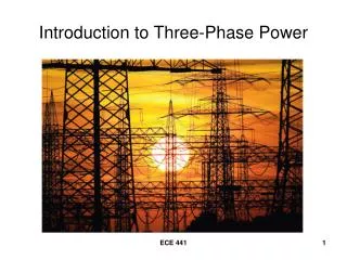
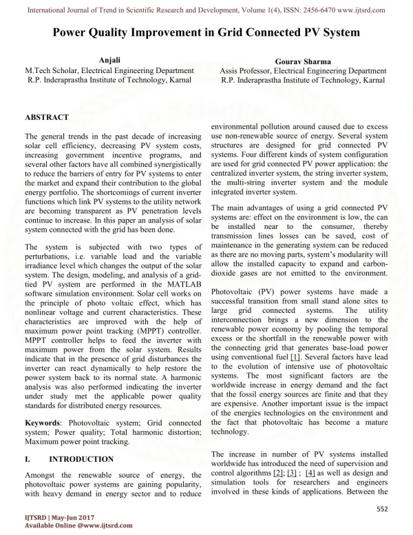
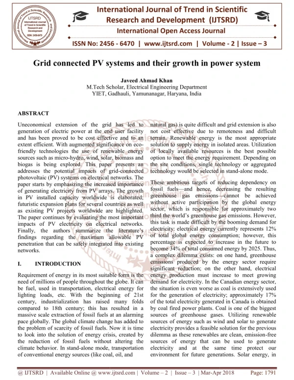
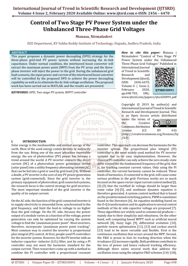
International Journal of Trend in Scientific Research and Development (IJTSRD) Volume 4 Issue 2, February 2020 Available Online: www.ijtsrd.com e-ISSN: 2456 – 6470 Control of Two Stage PV Power System under the Unbalanced Three-Phase Grid Voltages Manasa, Nirmaladevi EEE Department, KV Subba Reddy Institute of Technology, Dupadu, Andhra Pradesh, India ABSTRACT This paper proposes a dynamic power decoupling (DPD) strategy for the three-phase grid-tied PV power system without increasing the dc-link capacitance. Under normal condition, the interleaved boost converter will extract the maximum power point (MPP) from the PV array and the three- phase inverter will inject the power to the grid. During the unbalanced grid fault scenario, the input power and current of the interleaved boost converter will be controlled by the proposed DPD to achieve the power decoupling capability as well as to eliminate the dc-link voltage oscillation. The proposed work has been carried out in MATLAB, and the results are presented. KEYWORDS: DPD, Two stage PV system, MPPT controller How to cite this paper:Manasa | Nirmaladevi "Control of Two Stage PV Power System under the Unbalanced Three-Phase Grid Voltages" Published in International Journal of Trend in Scientific Research and Development (ijtsrd), ISSN: 2456-6470, Volume-4 | Issue-2, February 2020, pp.698-703, URL: www.ijtsrd.com/papers/ijtsrd30091.pdf Copyright © 2019 by author(s) and International Journal of Trend in Scientific Research and Development Journal. This is an Open Access article distributed under the terms of the Creative Commons Attribution License (CC (http://creativecommons.org/licenses/by /4.0) IJTSRD30091 BY 4.0) I. Solar energy is the inexhaustible and eternal energy of the earth. Most of the used energy comes directly or indirectly from the sun. Being one of the most attractive renewable energy, the use of photovoltaic (PV) power has become a trend around the world. A PV inverter converts the direct current (DC) of a photovoltaic power generation device (solar panel) into a utility frequency alternating current (AC) that can be fed into a grid or used by grid load [24]. Without a doubt, a PV inverter is the core of any PV power generation system (grid-connected). Since the grid inverter is, the primary equipment of photovoltaic grid connected systems, the research focus is the control strategy for grid inverters. The most important standard of the grid inverter is the quality of its output current. On the AC side, the function of the grid-connected inverter is to supply electricity in sinusoidal form, synchronized to the grid frequency, and limit the feed-in voltage to no higher than the grid voltage. On the DC side, because the power output of a module varies as a function of the voltage, power generation can only be optimized by varying the system voltage to find the \maximum power point". Most inverters, therefore, incorporate \maximum power point tracking". Most common way to control the inverter is proportional plus integral (PI) control. At first, people used PI controllers for the inverter system. However, for the PV inverter with an inductor-capacitor- inductor (LCL) filter, just by using a PI controller may not meet the harmonic standard for the output current. Then researchers come up with a method to combine the PI controller with a proportional resonant INTRODUCTION controller. This approach can decrease the harmonics for the inverter system. The proportional plus integral (PI) controller is the most widely used method for PV inverter systems due to its easy implementation. However, the classical PI controller can only achieve the zero steady-state error control for the fundamental frequency of the grid, that is, for tracking constant current values. Only using the PI controller, the current harmonic cannot be reduced. These kinds of harmonics, if connected to the grid, will cause some serious problem to the grid. Previous works are so much focused on the space vector input current control method [l], [3]-[5] that the rectified dc voltage should be larger than some value [4]-[5], and nonlinear dynamic equation is therefore generated. A system control method that is based on the predetermined switching pattern, PWM is sometimes found in the literature [6]. An equation modeling based on the D-Q transformation and its application to several control methods of the dc side capacitor voltage are proposed [7]. These algorithms are widely used in commercial products— mainly due to their simplicity and robustness. On the other hand, soft computing based MPPT such as artificial neural network [8], fuzzy logic [9], differential evolution [10], particle swarm optimization [11], [12] and cuckoo search [13] tend to be more versatile and flexible. First is the continuous oscillation that occurs around the MPP. Second, the P&O is prone to lose its tracking direction when the irradiance (G) increases rapidly. Both problems contribute to the loss of power and hence reduced tracking efficiency. Although there exists several work that address the oscillation issue using the adaptive P&O schemes [14]–[18], @ IJTSRD | Unique Paper ID – IJTSRD30091 | Volume – 4 | Issue – 2 | January-February 2020 Page 698
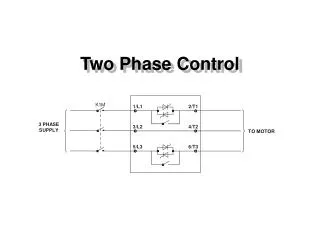
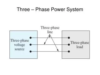
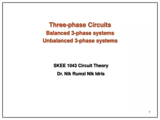
International Journal of Trend in Scientific Research and Development (IJTSRD) @ www.ijtsrd.com eISSN: 2456-6470 none has comprehensively address the loss of tracking direction–despite it being highlighted by [1], [5]. II. 3-PHASE GRID-CONNECTED PV SYSTEM The block diagram of a PV system connected to grid is shown in Fig.1. there needs to be a controller for each phase current. As the currents are sinusoidal non-linear controllers like dead beat and hysteresis are used in natural reference frame. To achieve power flow between the renewable resource generator and the utility network, the injected current needs to be synchronized with the grid voltage. Different algorithms are used for grid synchronization. The main purpose of these algorithms is to obtain the phase information of grid voltages. Transformation from natural reference frame to stationary or synchronous reference frame may be required to make this possible. To convert the DC voltage into an AC signal, the switches, present in an inverter, need to be switched on and off by providing pulses at their gates. There are a number of techniques that can be used to generate these pulses the most common being Space Vector based Pulse Width Modulation and Sine Pulse Width Modulation. As SPWM is used ought to be used in this work, it is therefore introduced here. In Sine wave based PWM, as the name suggests, a sine wave is used to modulate the carrier wave to generate switching signals. Fig. 2 shows the implementation of SPWM for a three phase, 2-level inverter. The frequency of reference sine waves dictates the frequency of fundamental component of generated waves. The frequency of carrier wave (triangular wave in figures) is the switching frequency of the inverter. In case of a two-level full-bridge voltage source inverter, there are six switches in total, with 2-switches in each leg for each phase. The pulses shown in Fig.2 are applied to the switches which are connected to positive dc bus rail in each leg, and a complimentary signal is applied to the switch connected to negative dc rail. This ensures that only a maximum of one switch is on at a time in a leg so that the DC bus does not get shorted. Inverters, as being switching devices cannot be directly connected to the grid. This is because the inverter produces harmonics which degrades power quality. (a) (b) Fig.1: Structure of a typical single-stage PV system A PV array consists of a number of PV modules or panels. A PV module is an assembly of a large number of interconnected PV cells [2]. The inverter in a PV system is employed to transform the DC-voltage generated from a PV module to a three-phase AC voltage. A three-phase inverter has three legs with two switches in each leg. The switching is performed by carrier-based or space-vector- based Pulse- Width Modulation (PWM). The output quantity of an inverter (voltage in VSI and current in CSI) is pulsed and Contains switching harmonics along with a 50 Hz fundamental. In order to separate the 50 Hz component, a filter is essential at the AC terminal of the inverter, where it is interfaced to the grid. Since the performance of the filter depends on the grid impedance, special care must be practiced in the filter design. III. CONTROL STRUCTURE OF GRID CONNECTED INVERTER Control system of a grid connected inverter is responsible for managing the power injection into the grid, obtained from a distributed generator. Mostly, a control structure based on two cascaded loops is employed for this purpose. Voltage control loop is responsible for balancing the power flow of the system. If there is more power available from the dc side, the controller present in this loop changes the reference current so that more ac power can be injected into the grid. The current loop deals with maintenance of power quality and reduction of harmonics present in the current, so that it can be injected into the grid. The control system can be designed in one of the three reference frames which are natural reference frame, stationary reference frame and synchronous reference frame. In natural reference frame, Fig.2: SPWM Transformers are expensive and bulky which leads to the system being costly. Therefore, a transformer-less topology to connect inverter to the grid has come into existence, and @ IJTSRD | Unique Paper ID – IJTSRD30091 | Volume – 4 | Issue – 2 | January-February 2020 Page 699
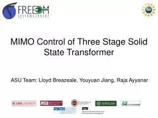
International Journal of Trend in Scientific Research and Development (IJTSRD) @ www.ijtsrd.com eISSN: 2456-6470 that is by using a filter circuit as the interface. There are three types of passive filters that are generally used; they are L, LC and LCL. These filters are shown in Fig.3. inverter will get the constant input DC voltage, which is necessary to improve the performance and efficiency of an inverter. Moreover, the cost of a boost converter is less compared to the other converters. Fig. 4 represents a basic illustration of a boost converter having input voltage Vin and output voltage Vo. During on switching, the diode will be reversed biased, and hence input current would be same as the inductor current. The output voltage during the on- interval would be the voltage across the capacitor. The value of the capacitor should be sufficiently large enough to maintain the constant voltage across the load. During the off- interval, the inductor will discharge in the reverse direction, which will cause a diode to become forward biased. The voltage across the inductor would be the difference between the input voltage and output voltage. The relation between the input voltage and output voltage can be derived using the volt-sec balance across the inductor. According to the volt- sec balance, the steady-state voltage across the inductor would be zero for one cycle. The boost converter can be designed in either continuous conduction mode (CCM) or discontinuous conduction mode (DCM). In CCM, the inductor current will be a non-zero value, whereas in DCM, the inductor current attains zero value and may have interleaved timing of zero inductor current for time (t). The two main factors for the boost converter design are the inductor and capacitor selection. The values of an inductor and a capacitor are finalized based on several factors. The selection of the capacitor is a very critical factor in regards to the overall performance of the boost converter. It should be sufficiently large to reduce the power oscillation towards the grid, and if not, then it may cause oscillation in the active and reactive power towards the grid. The typical boost control design contains a single closed loop control of the boost controller. These controllers may control the voltage or power through the boost controller. The resultant error from the controller will drive the PWM, which changes the duty ratio of the boost converter. The major disadvantage of the conventional single-loop uncontrollability of the current flowing through the boost converter. The current control is desired to inject the constant current into the inverter with fewer ripples. It can be achieved using the dual loop control, which contains an outer voltage loop and inner current control loop. In addition, the transfer function of the boost converter has zeros in the right half plane and a phase margin greater than 180. Therefore, the conventional voltage control method would not be sufficient for the boost control. The outer voltage loop here controls the constant PV terminal voltage, which generates the reference signal for the inner current loop. The error single from the inner current control loop drives the PWM of the boost converter. Power DC/DC converters have plenty of topologies, and the corresponding conversion technique is a big research topic. By an uncompleted statistics, there are more than 500 topologies of power DC/DC converters existing. Dr. F. L. Luo and Dr. H.Ye have firstly categorized all existing prototypes of the power DC/DC converters into six generations theoretically and evolutionarily since 2001. Their work is an outstanding contribution in the development of DC/DC conversion technology, and has been recognized and assessed by experts worldwide. The P&O algorithm is also called “hill-climbing”, but both names refer to the same algorithm depending on how it is implemented. Hill-climbing involves a perturbation on the Fig.3 L, LC and LCL filters Fig.4 Block Diagram of the two stage PV System A boost converter is used widely in renewable energy application such as solar generation and wind generation. Because of intermittency of solar and wind generation, it is very important to make the overall system efficient to counterbalance the effect of intermittency. The block diagram of the two stage PV System concept is shown in Fig.4. boost controller is the Fig. 5 Boost converter configuration A boost converter contributes towards improvement in efficiency of an overall system. A boost converter converts a low-voltage level to a high-voltage level. In addition, it regulates the power extracted from PV array along with the constant voltage application at the terminal output. The two- stage PV array connected to the grid will require a constant current injection in the DC-link, which is the output capacitor of the boost converter. A constant current injection will ensure the constant voltage of the DC-link and limited fluctuation in the output voltage variation. Hence, the @ IJTSRD | Unique Paper ID – IJTSRD30091 | Volume – 4 | Issue – 2 | January-February 2020 Page 700
International Journal of Trend in Scientific Research and Development (IJTSRD) @ www.ijtsrd.com eISSN: 2456-6470 duty cycle of the power converter and P&O a perturbation in the operating voltage of the DC link between the PV array and the power converter [8]. In the case of the Hill-climbing, perturbing the duty cycle of the power converter implies modifying the voltage of the DC link between the PV array and the power converter, so both names refer to the same technique. In this method, the sign of the last perturbation and the sign of the last increment in the power are used to decide what the next perturbation should be. If there is an increment in the power, the perturbation should be kept in the same direction and if the power decreases, then the next perturbation should be in the opposite direction. Based on these facts, the algorithm is implemented. The process is repeated until the MPP is reached. Then the operating point oscillates around the MPP. This problem is common also to the InCond method, as was mention earlier. A scheme of the algorithm is shown in Fig.5. Fig.5 The flowchart of the P&O Algorithm IV. This Section presents detailed simulation results of the proposed solar photovoltaic using DPD strategy and P&O MPPT. Simulation studies are carried out in the MATLAB/SIMULINK environment. Simulations are performed using MATLAB/SIMULINK software for tracking MPPs of the solar PV array. The solar PV panel provides a maximum output power at a MPP with VMPP and IMPP. R1 L SIMULATION RESULTS Universal Bridge Discrete, Ts = 5e-005 s. powergui g Diode + + A A Controlled Current Source + B B g C v - s - 25 - R2 IGBT C C C Subsystem1 VM1 Three-Phase Source Constant E T S I Ipv(A) Uout 1000 Constant1 V D I MPPT Fig. 6: Matlab Simulink model for two stage solar PV system The proposed DPD strategy is verified via the computer simulation software, MATLAB/Simulink, First. Fig.7, Fig.8 and Fig. 9 show simulation comparisons of the three-phase grid voltages, Vabc, the PV current, IPV, the PV power, PPV, the output power, Pout , the dc-link voltage, VDC , and the three phase output currents, Iabc under 5 kW operation. @ IJTSRD | Unique Paper ID – IJTSRD30091 | Volume – 4 | Issue – 2 | January-February 2020 Page 701
International Journal of Trend in Scientific Research and Development (IJTSRD) @ www.ijtsrd.com eISSN: 2456-6470 400 200 Vabc (V) 0 -200 -400 0.88 25 0.9 0.92 0.94 0.96 0.98 1 IPV (A) 20 15 10 0 0.1 0.2 0.3 0.4 0.5 0.6 0.7 0.8 0.9 1 6000 Ppv (W ) 5000 0 0.1 0.2 0.3 0.4 0.5 0.6 0.7 0.8 0.9 1 Pout (W ) 6000 5000 0.88 0.9 0.92 0.94 0.96 0.98 1 Vdc (V) 400 0 0 0.1 0.2 0.3 0.4 0.5 0.6 0.7 0.8 0.9 1 20 Iabc (A) 0 -20 0.88 0.9 0.92 0.94 0.96 0.98 1 Time (s) Fig.7 Simulation waveforms under normal operation 400 Vabc (V) 0 -400 0.88 25 0.9 0.92 0.94 0.96 0.98 1 Ipv(A) 20 15 10 0 0.1 0.2 0.3 0.4 0.5 0.6 0.7 0.8 0.9 1 6000 Ppv (W) 5000 4000 3000 0 0.1 0.2 0.3 0.4 0.5 0.6 0.7 0.8 0.9 1 Pout (W) 5000 3000 0 0.88 0.9 0.92 0.94 0.96 0.98 1 Vdc (V) 400 0 0.88 20 0.9 0.92 0.94 0.96 0.98 1 Iabc 0 -20 0.88 0.9 0.92 0.94 0.96 0.98 1 Time (s) Fig.8 Simulation waveforms without the DPD 400 Vabc (V) 0 -400 0.88 24 0.9 0.92 0.94 0.96 0.98 1 Ipv(A) 23.5 23 0 0.1 0.2 0.3 0.4 0.5 0.6 0.7 0.8 0.9 1 5100 Ppv(W) 5050 5000 4950 0 0.1 0.2 0.3 0.4 0.5 0.6 0.7 0.8 0.9 1 Pout (W) 5000 0 0.88 400 0.9 0.92 0.94 0.96 0.98 1 Vdc (V) 200 0 0.88 20 0.9 0.92 0.94 0.96 0.98 1 Iabc(A) 0 -20 0.88 0.9 0.92 0.94 0.96 0.98 1 Time (s) Fig.9 Simulation waveforms with the DPD @ IJTSRD | Unique Paper ID – IJTSRD30091 | Volume – 4 | Issue – 2 | January-February 2020 Page 702
International Journal of Trend in Scientific Research and Development (IJTSRD) @ www.ijtsrd.com eISSN: 2456-6470 [8]Syafaruddin, E. Karatepe, and T. Hiyama, “Artificial neural network-polar coordinated fuzzy controller based maximum power point tracking control under partially shaded conditions,” IET Renewable Power Generation, vol. 3, pp. 239–253, 2009. First, normal circuit operation waveforms are shown in Fig. 7. It can be seem that three-phase grid voltages and currents, Vabc and Iabc, shown in Fig. 7 (a) and Fig. 7(f) are balanced and there is no ripple on Poutand VDC, as shown in Fig. 7 (d) and Fig. 8 (e). The IPV and PPV shown in Fig. 7 (b) and Fig. 7 (c) are controlled by the MPPT algorithm and remain constant values. In order to demonstrate the unbalanced voltage fault scenario, one phase voltage of Vabcis reduced to 0.5 p.u. in both of the two simulations, as shown in Fig. 8 (a) and Fig.9 (a). V. CONCLUSIONS Detailed simulation results of solar PV panel using P&O to support the similar have been carried out in MATLAB, and the results are presented. In order to decouple the input- output power imbalance, the input current and power will be controlled via the DPD strategy to eliminate the dc-link oscillation. REFERENCES [1]T. Esram and P. L.Chapman, “Comparison of photovoltaic array maximum power point tracking techniques,” IEEE Trans. Energy Convers., vol. 22,no. 2, pp. 439–449, Jun. 2007. [9]B. N. Alajmi, K. H. Ahmed, S. J. Finney, and B. W. Williams, “A maximum power point tracking technique for partially shaded photovoltaic systems in micro- grids,” IEEE Trans. Ind. Electron., vol. 60, no. 4, pp. 1596–1606, Apr. 2013. [10]M. Seyedmahmoudian et al., “Simulation and hardware implementation of new maximum power point tracking technique for partially shaded PV system using hybrid DEPSO method,” IEEE Trans. Sustainable Energy, vol. 6, no. 3, pp. 850–862, Jul. 2015. [11]K. Ishaque and Z. Salam, “A deterministic particle swarm optimization maximum power point tracker for photovoltaic system under partial shading condition,” IEEE Trans. Ind. Electron., vol. 60, no. 8, pp. 3195– 3206, Aug. 2013. [12]H. Renaudineau et al., “A PSO-based global MPPT technique for distributed PV power generation,” IEEE Trans. Ind. Electron., vol. 62, no. 2, pp. 1047–1058, Feb. 2015. [2]Z. Salam, J. Ahmed, and B. S. Merugu, “The application of soft computing methods for MPPT of PV system: A technological and status review,” Appl. Energy, vol. 107, pp. 135–148, 2013. [13]J. Ahmed and Z. Salam, “A maximum power point tracking (MPPT) for PV system using Cuckoo search with partial shading capability,” Appl. Energy, vol. 119, pp. 118–130, 2014. [3]J. Ahmed and Z. Salam, “A critical evaluation on maximum power point tracking methods for partial shading in PV systems,” Renewable Sustainable Energy Rev., vol. 47, no. 7, pp. 933–953, 2015. [14]F. Zhang, K. Thanapalan, A. Procter, S. Carr, and J. Maddy, “Adaptive hybrid maximum power point tracking method for a photovoltaic system,” IEEE Trans. Energy Convers., vol. 28, no. 2, pp. 353–360, Jun. 2013. [4]H. A. Sher, A. F. Murtaza, A. Noman, K. E. Addoweesh, K. Al-Haddad, and M. Chiaberge, “A new sensorless hybrid MPPT algorithm based on fractional short-circuit current measurement and P&PO MPPT,” IEEE Trans. Sustainable Energy, vol. 6, no. 4, pp. 1426–1434, Oct. 2015. [15]R. Alonso, P. Ibaez, V. Martinez, E. Roman, and A. Sanz, “An innovative perturb, observe and check algorithm for partially shaded PV systems,” in Proc. 13th Eur. Conf. Power Electron. Appl., 2009, pp. 1–8. [5]M. A. Elgendy, B. Zahawi, and D. J. Atkinson, “Assessment of perturb and observe MPPT algorithm implementation techniques applications,” IEEE Trans. Sustainable Energy, vol. 3, no. 1, pp. 21–33, Jan. 2012. [16]S. K. Kollimalla and M. K. Mishra, “Variable perturbation size adaptive P&O MPPT algorithm for sudden changes in irradiance,” IEEE Trans. Sustainable Energy, vol. 5, no. 3, pp. 718–728, Jul. 2014. for PV pumping [6]E. Koutroulis, K. Kalaitzakis, and N. C. Voulgaris, “Development of a microcontroller-based, photovoltaic maximum power point tracking control system,” IEEE Trans. Power Electron., vol. 16, no. 1, pp. 46–54, Jan. 2001. [17]A. Pandey, N. Dasgupta, and A. K. Mukerjee, “High- performance algorithms for drift avoidance and fast tracking in solar MPPT system,” IEEE Trans. Energy Convers., vol. 23, no. 2, pp. 681–689, Jun. 2008. [18]W. Xiao and W. G. Dunford, “A modified adaptive hill climbing MPPT method for photovoltaic power systems,” in Proc. IEEE 35th Annu. Power Electron. Specialists Conf., 2004, pp. 1957–1963. [7]M. Qiang, S. Mingwei, L. Liying, and J. M. Guerrero, “A novel improved variable step-size incremental- resistance MPPT method for PV systems,” IEEE Trans. Ind. Electron., vol. 58, no. 6, pp. 2427–2434, Jun. 2011. @ IJTSRD | Unique Paper ID – IJTSRD30091 | Volume – 4 | Issue – 2 | January-February 2020 Page 703