Download
1 / 9
90 likes | 91 Views
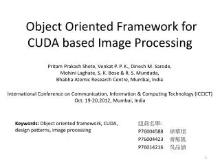
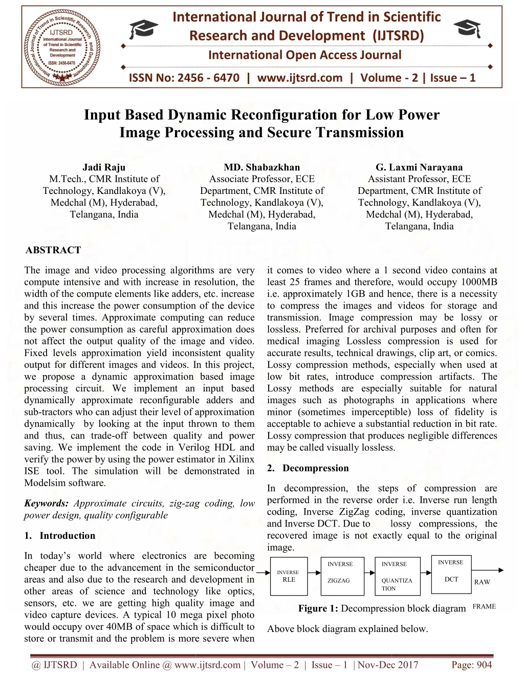
The fields of image and video encoding and compression have been put to a lot of stress with increase in the capacity of Integrated circuits. As technology shrinks, more and more transistors can be put into an I.C and thus the demand for higher resolution images and videos are coming up which need better encryption algorithms. The image and video processing algorithms are very compute intensive and with increase in resolution, the width of the compute elements like adders, etc. increase and this increase the power consumption of the device by several times. Approximate computing can reduce the power consumption as careful approximation does not affect the output quality of the image and video. Fixed levels approximation yield inconsistent quality output for different images and videos. In this project, we propose a dynamic approximation based image processing circuit. We implement an input based dynamically approximate reconfigurable adders and sub tractors who can adjust their level of approximation dynamically by looking at the input thrown to them and thus, can trade off between quality and power saving. We implement the code in Verilog HDL and verify the power by using the power estimator in Xilinx ISE tool. The simulation will be demonstrated in Modelsim software. Jadi Raju | MD. Shabazkhan | G. Laxmi Narayana "Input Based Dynamic Reconfiguration for Low Power Image Processing and Secure Transmission" Published in International Journal of Trend in Scientific Research and Development (ijtsrd), ISSN: 2456-6470, Volume-2 | Issue-1 , December 2017, URL: https://www.ijtsrd.com/papers/ijtsrd7043.pdf Paper URL: http://www.ijtsrd.com/engineering/chassis-engineering/7043/input-based-dynamic-reconfiguration-for-low-power--image-processing-and-secure-transmission/jadi-raju<br>

E N D
International Research Research and Development (IJTSRD) International Open Access Journal International Open Access Journal International Journal of Trend in Scientific Scientific (IJTSRD) ISSN No: 2456 - 6470 | www.ijtsrd.com | Volume Input Based Dynamic Reconfiguration for Low Power nd Secure Transmission ISSN No: 2456 | www.ijtsrd.com | Volume - 2 | Issue – 1 Input Based Dynamic Reconfiguration Image Processing a Image Processing and Secure Transmission or Low Power Jadi Raju MD. Shabazkhan Associate Professor, ECE Department, CMR Institute of Technology, Kandlakoya (V), Medchal (M), Hyderabad, Telangana, India Laxmi Narayana Assistant Professor, ECE Department, CMR Institute of Technology, Kandlakoya (V), Medchal (M), Hyderabad, Telangana, India G. Laxmi Narayana Assistant Professor, ECE Department, Technology, Medchal (M), Telangana, India M.Tech., CMR Institute of Technology, Kandlakoya (V), Medchal (M), Hyderabad, Telangana, India ABSTRACT The image and video processing algorithms are very compute intensive and with increase in resolution, the width of the compute elements like adders, etc. increase and this increase the power consumption of the device by several times. Approximate computing can reduce the power consumption as careful approximation does not affect the output quality of the image and video. Fixed levels approximation yield inconsistent quality output for different images and videos. In this project, we propose a dynamic approximation based image processing circuit. We implement an input based dynamically approximate reconfigurable adders and sub-tractors who can adjust their level of approximation dynamically by looking at the input thrown to them and thus, can trade-off between quality and power saving. We implement the code in Verilog HDL and verify the power by using the power estimator in Xilinx ISE tool. The simulation will be demonstrated in Modelsim software. The image and video processing algorithms are very compute intensive and with increase in resolution, the width of the compute elements like adders, etc. increase and this increase the power consumption of the device it comes to video where a 1 second video contains at least 25 frames and therefore, would occupy 1000MB i.e. approximately 1GB and hence, there is a necessity to compress the images and videos for storage and transmission. Image compression may be lossy or lossless. Preferred for archival purposes and often for medical imaging Lossless compression is used for accurate results, technical drawings, clip art, or comics. Lossy compression methods, especially when used at low bit rates, introduce compression artifacts. The Lossy methods are especially suitable for natural images such as photographs in applications where minor (sometimes imperceptible) loss of fidelity is acceptable to achieve a substantial reduction in bit rate. Lossy compression that produces negligible differences it comes to video where a 1 second video contains at least 25 frames and therefore, would occu i.e. approximately 1GB and hence, there is a necessity to compress the images and videos for storage and transmission. Image compression may be lossless. Preferred for archival purposes and often for medical imaging Lossless compression is used for accurate results, technical drawings, clip art, or comics. Lossy compression methods, especially when used at low bit rates, introduce compression Lossy methods are especially suitable for natural images such as photographs in applications where minor (sometimes imperceptible) loss of fidelity is acceptable to achieve a substantial reduction in bit rate. Lossy compression that produces may be called visually lossless. may be called visually lossless. computing can reduce the power consumption as careful approximation does not affect the output quality of the image and video. Fixed levels approximation yield inconsistent quality output for different images and videos. In this project, ic approximation based image processing circuit. We implement an input based dynamically approximate reconfigurable adders and tractors who can adjust their level of approximation dynamically by looking at the input thrown to them off between quality and power saving. We implement the code in Verilog HDL and verify the power by using the power estimator in Xilinx ISE tool. The simulation will be demonstrated in 2.Decompression In decompression, the steps of compression are performed in the reverse order i.e. Inverse run length coding, Inverse ZigZag coding, inverse quantization In decompression, the steps of compression are performed in the reverse order i.e. Inverse run length coding, Inverse ZigZag coding, inverse quantization and Inverse DCT. Due to recovered image is not exactly equal to the original image. Keywords: Approximate circuits, zig-zag power design, quality configurable zag coding, low lossy lossy compressions, the recovered image is not exactly equal to the original 1.Introduction In today’s world where electronics are becoming cheaper due to the advancement in the semiconductor areas and also due to the research and development in other areas of science and technology like optics, sensors, etc. we are getting high quality image and video capture devices. A typical 10 mega pixel photo would occupy over 40MB of space which is difficult to store or transmit and the problem is more severe when store or transmit and the problem is more severe when In today’s world where electronics are becoming cheaper due to the advancement in the semiconductor areas and also due to the research and development in other areas of science and technology like optics, sensors, etc. we are getting high quality image and video capture devices. A typical 10 mega pixel photo would occupy over 40MB of space which is difficult to INVERSE INVERSE RLE INVERSE INVERSE INVERSE DCT ZIGZAG QUANTIZA TION TION QUANTIZA RAW FRAME Figure 1: Decompression block diagram Decompression block diagram Above block diagram explained below. Above block diagram explained below. @ IJTSRD | Available Online @ www.ijtsrd.com @ IJTSRD | Available Online @ www.ijtsrd.com | Volume – 2 | Issue – 1 | Nov-Dec 2017 Dec 2017 Page: 904
Inverse Run length International Journal of Trend in Scientific Research and Development (IJTSRD) ISSN: 2456 International Journal of Trend in Scientific Research and Development (IJTSRD) ISSN: 2456 International Journal of Trend in Scientific Research and Development (IJTSRD) ISSN: 2456-6470 The compressed frame is passed through the inverse run length encoding process. The inverse run length encoder reads the marker which says the quantity of repetition of its succeeding character and outputs the value quantity number of times thus giving the same output of the zigzag encoder in the compression scheme output of the zigzag encoder in the compression scheme The compressed frame is passed through the inverse h encoding process. The inverse run length encoder reads the marker which says the quantity of repetition of its succeeding character and outputs the value quantity number of times thus giving the same Inverse zigzag Inverse Zigzag process re arranges the values of the matrix received in the order before they were scrambled by the ZigZag transformation in the compression scheme. The output of the Inverse zigzag should look exactly like the output of the Quantization step in the quantization process. Inverse Zigzag process re arranges the values of the matrix received in the order before they were scrambled transformation in the compression scheme. The output of the Inverse zigzag should look exactly like the output of the Quantization step in the The above matrices show that there are slight differences between original image and decompressed image but, the above compression reduces 70% space The above matrices show t differences between original image and decompressed image but, the above compression reduces 70% space or bandwidth. Inverse Quantization 3.Approximate Computing Approximate Computing Inverse quantization multiplies each of the matrix variable by the corresponding quality matrix variable. This is not a matrix multiplication but, only an element by element multiplication. Since quantization is a lossy transformation, inverse quantization does not yield the exact result as the output of the DCT pr reduction in quality is the price we pay for the compression. Inverse quantization multiplies each of the matrix by the corresponding quality matrix variable. This is not a matrix multiplication but, only an element by element multiplication. Since quantization is a lossy transformation, inverse quantization does not yield the exact result as the output of the DCT process. The reduction in quality is the price we pay for the Approximate computing has made its way into image Approximate computing has made its way into image and signal processing big generation where the algorithms used are compute extensive and slower machines are not preferred for automation these days. In this project we replace the ripple carry adders with their approximate version Reconfigurable adder/ subtra Reconfigurable Adder/Subtractor Blocks Dynamic variation of the DA can be done when each often adder/subtractor blocks is equipped with one or more of its approximate copies and it is able to switch between them as per requirement. architecture can include any approximate version of the adders/subtractors. As a reference, Gupta et proposed six different kinds of approximate circuits for adders. However, it also needs to be ensured that the additional area overheads required the reconfigurable approximate circuits are minimal with sufficiently large examples, we have chosen the two most naive methods presented, namely, truncation and approximation 5, for approximating the adder/subtractor latter one can also be conceptualized as an enhanced version of truncation as it just relays the two 1 inputs, one as Sum and the other (Choice 2). In case A, B, and Cin are the 1 the full adder (FA), then the outputs are Sum = B and Cout = A. The resultant truth- outputs are correct for more than half of all input combinations, thus proving to be a better approximation mode than truncation. The proposed scheme replace each FA cell of the adders/subtractors with a FA (DMFA) cell (Figure 3.1)in which operate either in fully accurate or in some operate either in fully accurate or in some time time in in the the current current generation where the algorithms used are compute slower machines are not preferred for automation these days. In this project we replace the ripple carry adders with their approximate version Reconfigurable adder/ subtractor blocks (RABs). Reconfigurable Adder/Subtractor Blocks Dynamic variation of the DA can be done when each often adder/subtractor blocks is equipped with one or more Inverse DCT and it is able to switch quirement. This reconfigurable can include any approximate version of reference, Gupta et al. proposed six different kinds of approximate circuits for adders. However, it also needs to be ensured that the overheads required for the reconfigurable approximate circuits are minimal large examples, we have chosen the two most naive methods , namely, truncation and approximation 5, for adder/subtractor latter one can also be conceptualized as an enhanced version of truncation as it just relays the two 1-bit inputs, one as Sum and the other (Choice 2). In case A, B, and Cin are the 1-bitinputs to er (FA), then the outputs are Sum = B and Inverse DCT is the exact inverse transformation of the DCT transformation. As a result of the inverse DCT process the matrix changes from the frequency domain to the amplitude domain and we can see the pixel values now. The decompressed image is not exactly like the original image as we have lost some information due to quantization and some information due to the rounding off in DCT and IDCT. due to the rounding off in DCT and IDCT. Inverse DCT is the exact inverse transformation of the DCT transformation. As a result of the inverse DCT process the matrix changes from the frequency domain tude domain and we can see the pixel values now. The decompressed image is not exactly like the original image as we have lost some information due to quantization and some information constructing power power savings. savings. As As blocks. blocks. The The as Carry Out -table [10] shows that the than half of all input combinations, thus proving to be a better approximation mode than truncation. The proposed scheme replaces the adders/subtractors with a dual-mode MFA) cell (Figure 3.1)in which each FA cell can @ IJTSRD | Available Online @ www.ijtsrd.com @ IJTSRD | Available Online @ www.ijtsrd.com | Volume – 2 | Issue – 1 | Nov-Dec 2017 Dec 2017 Page: 905
approximation mode depending on the state other control signal APP.A logic high value of the APP signal denotes that the DMFA is operating in the approximate mode. International Journal of Trend in Scientific Research and Development (IJTSRD) ISSN: 2456-6470 original FA block. This difference in power can be attributed mainly to the increase in load capacitance of the FA block due to the addition of the input capacitance of the interfaced multiplexers. A small portion of the total power is contributed by the additional switching of the multiplexers. Table I also shows that the power consumed during DMFA approximate mode is almost negligible when compared with the accurate mode, which is due to the power gating of the FA block by the pMOS transistor, as shown in Figure 3.1. Reduction in the input switching activity of the multiplexers is also a secondary cause for this small amount of power. We term these adders/subtractors as RABs. It is significant to note that the FA cell is power-gated when operating in the approximate mode. Our experiments have shown a negligible difference in the power consumption of DMFA when operated in either of the two approximation modes. Hence, without any loss of generality, approximation 5 was chosen for its higher probability of giving the correct output result than truncation, which invariably outputs 0 irrespective of the input. 4.RESULTS 4.1 SIMULATION and SYNTHESIS RESULTS In this section, we show the simulation results of various blocks like DCT, quantization, zigzag and run length encoding. We are starting with the given matrix Figure 2: bit DMFA Figure 2 shows the logic block diagram of the DMFA cell, which replaces the constituent FA cells of an 8-bit RCA, This undermines the primary objective as most of the power savings that we get from approximating the bits are lost. Instead, the two-mode decoder and the 2:1 multiplexers have negligible overhead and also provide sufficient command over the approximation degree.1) DMFA Overhead: The power gating transistor and the multiplexers of the DMFA are designed to incur the least possible overhead. Inverse RLE Simulation Output: Our experiments show that switching power of the CMOS transistors contributes toward most of the total power consumption of the FA and DMFA blocks. Table I presents the power consumption of FA and DMFA for different modes obtained by exhaustive simulation in Synopsys NanoSim. It shows that the power increases by 0.21 μW when we operate DMFA in accurate mode as compared with the Figure 3:Inverse RLE Output @ IJTSRD | Available Online @ www.ijtsrd.com | Volume – 2 | Issue – 1 | Nov-Dec 2017 Page: 906
International Journal of Trend in Scientific Research and Development (IJTSRD) ISSN: 2456-6470 The Figure 3 shows the Inverse RLE Output compressed frame is passed through the inverse run length encoding process. The inverse run length encoder reads the marker which says the quantity of repetition of its succeeding character and outputs the value quantity number of times thus giving the same output of the zigzag encoder in the compression scheme. Inverse Zig Zag Simulation Output: RTL Schematic of Inverse RLE Figure 6: Inverse Zig Zag Output Above figure-6 shows the Inverse Zigzag process re arranges the values of the matrix received in the order before they were scrambled transformation in the compression scheme. The output of the Inverse zigzag should look exactly like the output of the Quantization step in the quantization process. by the ZigZag Synthesis summary of Inverse RLE Figure 4: RTL schematic of inverse RLE Above figure 4 shows 4 RTL schematic of inverse RLE. In this schematic all resisters and transistors are in a logic is employed and resultant output generated. TECH schematic of inverse RLE Figure 7 Synthesis summary of Inverse RLE Above figure 7 shows Synthesis summary of Inverse RLE in this all the values of the image pixel values in this Synthesis summary are arranged. Figure 5: TECH schematic of inverse RLE. Above figure 5 shows TECH schematic of inverse RLE. @ IJTSRD | Available Online @ www.ijtsrd.com | Volume – 2 | Issue – 1 | Nov-Dec 2017 Page: 907
International Journal of Trend in Scientific Research and Development (IJTSRD) ISSN: 2456-6470 RTL schematic of Inverse of RLE Synthesis summary of Inverse ZIG ZAG Figure 8 RTL schematic of Inverse of RLE Figure 8 shows the RTL schematic of Inverse of RLE. It consist of resister and transistors it arranging number of image are expending and showing into next step Figure 10: Synthesis summary of Inverse ZIG ZAG Above figure 10 shows Synthesis summary of Inverse ZIG ZAG in this all the values of the image pixel values in this Synthesis summary. TECH Schematic of Inverse RLE RTL schematic of Inverse ZIG ZAG Figure 9 TECH Schematic of Inverse RLE Above figure 9 shows TECH schematic of inverse RLE. Figure 11 RTL schematic of Inverse ZIG ZAG. Above figure 11 shows the schematic of Inverse ZIG ZAG in this all resisters and transistor are arranged to arrange the all image pixel values are re-arranged in proper. @ IJTSRD | Available Online @ www.ijtsrd.com | Volume – 2 | Issue – 1 | Nov-Dec 2017 Page: 908
International Journal of Trend in Scientific Research and Development (IJTSRD) ISSN: 2456-6470 Tech Schematic of Inverse ZIG Zag Synthesis summary of Inverse quant Figure 12 Tech Schematic of Inverse ZIG Zag. Above Figure 12 shows Tech Schematic of Inverse ZIG Zag . Inverse Quantization SimulationOutput: Figure 14 Synthesis summary of Inverse quant above figure 14 shows Synthesis summary of Inverse quant in this all the values of the image pixel values in matrix Synthesis summary. RTL schematic of inverse QUANT Figure 13 Inverse Quantization Output In Quantization We can clearly see that the higher frequency components have become zero figure 13 shows the Inverse Quantization Output but in inverse Quantization higher frequencies also present it means the recovered. Figure 15 RTL schematic of inverse QUANT Above figure 15 shows the schematic of inverse QUANT in this all resisters and transistor are arranged to arrange the all image pixel values are re-arranged in proper. @ IJTSRD | Available Online @ www.ijtsrd.com | Volume – 2 | Issue – 1 | Nov-Dec 2017 Page: 909
TECH schematic of Inverse QUANT International Journal of Trend in Scientific Research and Development (IJTSRD) ISSN: 2456-6470 Synthesis summary of DECODER Figure 19: Synthesis summary of DECODER Abe figure 19 shows the Synthesis summary of DECODER and which values are taken in the decoder is shown in this summary. TECH schematic of Decoder Figure 16: TECH schematic of Inverse QUANT Above Figure 16 shows Tech Schematic of Inverse QUANT. Synthesis summary of Inverse DCT Figure 20 TECH schematic of Decoder. Above Figure 20 shows Tech Schematic of Decoder. Synthesis summary of Top Module Figure 17 Synthesis summary of Inverse DCT Above figure 17 shows Synthesis summary of Inverse DCT in this all the values of the image pixel values in matrix Synthesis summary mathematically in this. Figure 21: Synthesis summary of Top Module TECHschematic of Inverse DCT Above figure 21 shows Synthesis summary of Top Module in this decoder values are shows it consist the total summary of the decoder. TECH schematic of Top module Figure 18 RTL schematic of Inverse DCT Above Figure 18 shows Tech Schematic of Inverse DCT. @ IJTSRD | Available Online @ www.ijtsrd.com | Volume – 2 | Issue – 1 | Nov-Dec 2017 Page: 910
Figure 22 RTL schematic of Top module International Journal of Trend in Scientific Research and Development (IJTSRD) ISSN: 2456-6470 876, Jun. 1995. 3.I. S. Chong and A. Ortega, “Dynamic voltage scaling algorithms forpower constrained motion estimation,” in Proc. Acoust.,Speech, Signal Process. (ICASSP), vol. 2. Apr. 2007, pp. II-101–II-104. Above Figure 22 shows the RTL schematic of Top module of the decoder and it showing number of pins in the decoder. IEEE Int. Conf. 5. SUMMARY 5.1 APPLICATIONS 4.I. S. Chong and A. Ortega, “Power efficient motion estimation usingmultiple computations,” in Proc. IEEE Int. Conf.Multimedia Expo, Jul. 2007, pp. 2046–2049. DCT is used mostly in Image compression and image encoding. High speed approximate image compression can be used in imprecise metric High speed camera circuits like professional photography, high performance mobile cameras, etc. 5.D. Mohapatra, G. Karakonstantis, and K. Roy, “Significance drivencomputation: scalable, variation-aware, motionestimator,” in Proc. 14th ACM/IEEE Int. Symp. Low Power Electron.Design (ISLPED), 2009, pp. 195–200. A quality-tuning voltage- High speed image processing such as facial recognition circuits and electronic microscopes. High speed image processing like analyzing images taken by satellites, space telescopes, etc. 6.J. George, B. Marr, B. E. S. Akgul, and K. V. Palem, “Probabilisticarithmetic and energy efficient embedded signal processing,” in Proc.Int. Conf. Compil., Archit., Synth. Embedded Syst. (CASES), 2006,pp. 158–168. 5.2 CONCLUSION We have successfully implemented the approximate adder circuit 7.D. Shin and S. K. Gupta, “A re-design technique for datapath modulesin error tolerant applications,” in Proc. 17th Asian Test Symp. (ATS),2008, pp. 431– 437. We have applied the approximate adder in the DCT circuit and we have demonstrated the functioning of DCT with approximate adders. We have implemented the entire image encoding flow – DCT, Quantization, ZigZag encoding and Run length encoding. 8.S. Venkataramani, A. Sabne, V. Kozhikkottu, K. Roy, andA. Raghunathan, “SALSA: Systematic logic synthesis of approximatecircuits,” in Proc. 49th Annu. Design Autom. Conf. (DAC), Jun. 2012,pp. 796–801. We compression ratios with variations in quality levels. have demonstrated the variations in 9.V. Gupta, D. Mohapatra, S. P. Park, A. Raghunathan, andK. Roy, “IMPACT: IMPrecise adders for low-power approximatecomputing,” in Proc. 17th IEEE/ACM Int. Symp. Low-Power Electron.Design (ISLPED), Aug. 2011, pp. 409– 414. 5.3 FUTURE SCOPE The circuit can be further improved by converting the 2D DCT into approximate DCT which can be implemented without any multipliers and thus, the circuit complexity decreases greatly. 10.V. Gupta, D. Mohapatra, A. Raghunathan, and K. Roy, “Lowpowerdigital signal processing using approximate adders,” IEEETrans. Comput.-Aided Design Integr. Circuits Syst., vol. 32, no. 1,pp. 124– 137, Jan. 2013. There are approximate multipliers which have been proposed in some recent works which will further help in increasing the speed. REFERENCES 1.M. Elgamel, A. M. Shams, and M. A. Bayoumi, “A comparative analysis for low power motion estimation VLSI architectures,” in Proc. IEEE Workshop Signal Process. Syst. (SiPS), Oct. 2000, 11.V. G. Moshnyaga, K. Inoue, and M. Fukagawa, “Reducing energyconsumption of video memory by bit-width compression,” in Proc. Int.Symp. Low Power Electron. Design (ISLPED), 2002, pp. 142– 147. 2.F. Dufaux and F. Moscheni, “Motion estimation techniques for digital TV: A review and a new contribution,” Proc. IEEE, vol. 83, no. 6,pp. 858– 12.Z. He and M. L. Liou, “Reducing hardware complexity of motionestimation algorithms using @ IJTSRD | Available Online @ www.ijtsrd.com | Volume – 2 | Issue – 1 | Nov-Dec 2017 Page: 911
International Journal of Trend in Scientific Research and Development (IJTSRD) ISSN: 2456-6470 truncated pixels,” in Proc. IEEE Int. Symp.Circuits Syst. (ISCAS), vol. 4. Jun. 1997, pp. 2809–2812. Authors Profile: 13.Z.-L. He, C.-Y. Tsui, K.-K. Chan, and M. L. Liou, “Low-power VLSIdesign for motion estimation using adaptive pixel truncation,” IEEETrans. Circuits Syst. Video Technol., vol. 10, no. 5, pp. 669–678,Aug. 2000. Jadi.Raju received his bachelor’s degree in 2015 in electronics and communication engineering from JJ institute of technology, India which is affiliated with JNTU Hyderabad, India. His areas of interest include VLSI design. He is pursuing his M-Tech in VLSI SYSTEM DESIGN from CMR Institute of Technology. 14.A. Raha, H. Jayakumar, and V. Raghunathan, “A power efficient videoencoder using reconfigurable approximate arithmetic units,” in Proc.27th Int. Conf. VLSI Design, 13th Int. Conf. Embedded Syst., Jan. 2014,pp. 324–329. Mr. Mohammad Shahbaz Khan M.TECH (PhD), Associate Professor, ECE Department, CMRIT, He has 10 years of teaching experience. He has worked as Associate Professor in various Engineering colleges under JNTUH such as Amina institute of Technology, he coordinated &organized many workshops, FDP and contributed 20 papers to various conference & Journals 15.P. M. Kuhn, Algorithms, Complexity Analysis and VLSI Architecturesfor MPEG-4 Motion Estimation, 1st ed. Norwell, MA, USA: Kluwer,1999. 16.K. Seshadrinathan, R. Soundararajan, A. C. Bovik, and L. K. Cormack,“Study of subjective and objective quality assessment of video,” IEEETrans. Image Process., vol. 19, no. 6, pp. 1427–1441, Jun. 2010. Mr.G.Lakshminarayana M.Tech (Ph.D), Assistant professor, ECE Department, CMRIT. He has completed M.Tech with specialization in Digital Systems and Computer Electronics (D.S.C.E) from JNTUHCE (Autonomous), Hyderabad in 2010 and A.M.I.E (E.C.E) from IEI, Kolkata, India in winter 2004.He has 12 Years of academic experience at Various Engineering Colleges. He has immense research and academic experience in Digital Systems. His Research Areas of Interest are VLSI, Digital Systems and Embedded Systems. 17.S. Winkler, “Video quality measurement standards—Current status andtrends,” in Proc. 7th Int. Conf. Inf., Commun., Signal Process. (ICICS),Dec. 2009, pp. 1–5. 18.Xiph.org. (2013). Xiph Video Test Media. [Online]. Available:http://media.xiph.org/video/derf/ 19.Wikipedia. (2013). Carry-Select Adder—From Wikipedia, the Free Available: http://en.wikipedia.org/w/index.php?title=Carry- select_adder&oldid=572157817, accessed Jan. 30, 2014. Encyclopedia.[Online]. @ IJTSRD | Available Online @ www.ijtsrd.com | Volume – 2 | Issue – 1 | Nov-Dec 2017 Page: 912