Download
1 / 4
60 likes | 82 Views
In a modern power system, electrical energy from the generating station is delivered to the consumers through a network of transmission and distribution. Transmission lines are also important elements of electric power system and require attention of protecting for safety against the possible faults occurring on them. The detection of a fault and disconnection of a faulty section or apparatus can be achieved by using fuses or relays in conjunction with circuit breakers. Distance relay has the ability to detect a fault within a distance along a transmission line or cable from its location. Distance relay protection is the most widely used in case of high voltage and extra high voltage in the transmission line. In this paper discussion about how to protect the long transmission line with distance relay. June Tharaphe Lwin | Christ Tine Lin "Consideration of Three Phase Faults on Transmission Line with Distance Protection" Published in International Journal of Trend in Scientific Research and Development (ijtsrd), ISSN: 2456-6470, Volume-3 | Issue-5 , August 2019, URL: https://www.ijtsrd.com/papers/ijtsrd28013.pdf Paper URL: https://www.ijtsrd.com/engineering/electrical-engineering/28013/consideration-of-three-phase-faults-on-transmission-line-with-distance-protection/june-tharaphe-lwin<br>

E N D
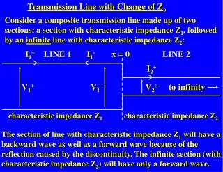
International Journal of Trend in Scientific Research and Development (IJTSRD) Volume 3 Issue 5, August 2019 Available Online: www.ijtsrd.com e-ISSN: 2456 – 6470 Consideration of Three Phase Faults on Transmission Line with Distance Protection June Tharaphe Lwin, Christ Tine Lin Department of Electrical Power Engineering, Technological University, Loikaw, Myanmar How to cite this paper: June Tharaphe Lwin | Christ Tine Lin "Consideration of Three Phase Faults on Transmission Line with Distance Protection" Published in International Journal of Trend in Scientific Research and Development (ijtsrd), ISSN: 2456- 6470, Volume-3 | Issue-5, August 2019, pp.2296-2299, https://doi.org/10.31142/ijtsrd28013 Copyright © 2019 by author(s) and International Journal of Trend in Scientific Research and Development Journal. This is an Open Access article distributed under the terms of the Creative Commons Attribution License (CC (http://creativecommons.org/licenses/by /4.0) The detection of a fault and disconnection of a faulty section or apparatus can be achieved by using fuses or relays in conjunction with circuit breakers. A fuse performs both detection and interruption functions automatically but its use is limited for the protection of low-voltage circuits only. For high voltage circuits (above 3·3 kV), relays and circuit breakers are employed to serve the desired function of automatic protective gear. The relays detect the fault and supply information to the circuit breaker which performs the function of circuit interruption. Basically, distance relay determines the impedance of the fault portion of a transmission line from the measured voltages and currents at the relay location. Distance relay can be used to protect the transmission line or power transformers. Transmission lines can vary in length from several hundred feet to several hundred miles and in-voltage. Distance protection is the primary protection of high voltage (HV) and extra high voltage (EHV) power transmission line. It detects disturbance (such as short circuit currents) by measuring the impedance between the faults point and the relay location. The impedance values are obtained by dividing the voltage and current at the relay location .Distance protection needs to operate as quickly as possible for an internal fault condition, while is also must be able to discriminate between internal and external faults to prevent unnecessary disconnection of the healthy system. ABSTRACT In a modern power system, electrical energy from the generating station is delivered to the consumers through a network of transmission and distribution. Transmission lines are also important elements of electric power system and require attention of protecting for safety against the possible faults occurring on them. The detection of a fault and disconnection of a faulty section or apparatus can be achieved by using fuses or relays in conjunction with circuit breakers. Distance relay has the ability to detect a fault within a distance along a transmission line or cable from its location. Distance relay protection is the most widely used in case of high voltage and extra high voltage in the transmission line. In this paper discussion about how to protect the long transmission line with distance relay. KEYWORDS: Power system, Generating Station, Transmission Line, Distance Relay Protection, Detection of Fault I. INTRODUCTION TO POWER SYSTEM PROTECTION In a power system consisting of generators, transformers, transmission and distribution circuits, it is inevitable that sooner or later some failure will occur somewhere in the system. When a failure occurs on any part of the system, it must be quickly detected and disconnected from the system. There are two principal reasons for it. Firstly, if the fault is not cleared quickly, it may cause unnecessary interruption of service to the customers. Secondly, rapid disconnection of faulted apparatus limits the amount of damage to it and prevents the effects of fault from spreading into the system. II. DISTANCE OPERATINGPRINCIPLE The operation of the relays is so far depended upon the magnitude of current or power in the protected circuit. However, there is another group of relays in which the operation is governed by the ratio of applied voltage to current in the protected circuit. Such relays are called distance or impedance relays. In an impedance relay, the torque produced by a current element is opposed by the torque produced by a voltage element. The relay will operate when the ratio V/I is less than a predetermined value. It acts as the main protection for overhead transmission lines and provides back-up protection. Distance relay functions have been in use for many years and have progressed from the original electromechanical types through analog types and now up to digital types of functions. The purpose is to be described the one type of relay which functions depending upon the distance of fault in the line or cable. These relays are known as distance relay or impedance relay. As transmission lines are frequently subjected to various kinds of faults different protection schemes are evolved for the effective protection of transmission lines. Figure 1 illustrates the basic principle of operation of an impedance relay. The voltage element of the relay is excited through a potential transformer (P.T.) from the line to be protected. The current element of the relay is excited from a current transformer (C.T.) in series with the line. The portion IJTSRD28013 BY 4.0) RELAY PROTECTION AND @ IJTSRD | Unique Paper ID – IJTSRD28013 | Volume – 3 | Issue – 5 | July - August 2019 Page 2296
International Journal of Trend in Scientific Research and Development (IJTSRD) @ www.ijtsrd.com eISSN: 2456-6470 AB of the line is the protected zone. Under normal operating conditions, the impedance of the protected zone is ZL. The relay is so designed that it closes its contacts whenever impedance of the protected section falls below the pre- determined value that is ZL in this case. Figure.1 Basic principle of operation of an impedance relay[2] When a fault occurs at point F1 in the protected zone, the impedance Z (= *V/I) between the point where the relay is installed and the point of fault will be less than ZL and hence the relay operates. The fault occurs beyond the protected zone (point F2), the impedance Z will be greater than ZL and the relay does not operate. A distance or impedance relay is essentially an ohmmeter and operates whenever the impedance of the protected zone falls below a pre-determined value. There are two types of distance relays in use for the protection of power supply, namely; A.Definite-distance relay which operates instantaneously for fault up to a pre-determined distance from the relay. B.Time-distance relay in which the time of operation is proportional to the distance of fault from the relay point. A fault nearer to the relay will operate it earlier than a fault farther away from the relay. A.R–X Diagram In general, all electromechanical relays respond to one or more of the conventional torque producing input quantities: (i) voltage, (ii) current, (iii) product of voltage, current, and the angle θ between them, and (iv) a physical or design force such as a control spring. Similar considerations hold for solid-state relays as well. For the product-type relay, such as the distance relay, analyzing the response of the relay for all conditions is difficult because the voltage varies for each fault or varies for the same fault but with different system conditions. To resolve this difficulty, it is common to use an R–X diagram to both analyze and visualize the relay response. By utilizing only two quantities, R and X (or Z and θ), avoid the confusion introduced using the three quantities E, I, and θ. There is an additional significant advantage, in that the R–X diagram allows representing both the relay and the system on the same diagram. The ratio of E and I at the relay location is an impedance under all circumstances, and when a fault occurs, this impedance assumes the value Zf. In general, the ratio E/I is known as the apparent impedance seen by the relay. This impedance may be plotted as a point on the complex R–X plane. This is the plane of (apparent) secondary ohms. It could view the impedance as the voltage pharos, provided that the current is assumed to be the reference pharos, and of unit magnitude. Figure.2 R–X diagram as a special case of the pharos diagram (pf, power factor)[3] III. On a three-phase power system, there are 10 distinct types of possible faults: a three-phase fault, three phase-to-phase faults, three phase-to-ground faults, and three double-phase- to ground faults. The equations that govern the relationship between voltages and currents at the relay location is different for each of these faults. It will take several distance relays, each of them energized by a different pair of voltage and current inputs to measure the distance to the fault correctly. It is a fundamental principle of distance relaying that, regardless of the type of fault involved, the voltage and current used to energize the appropriate relay are such that the relay will measure the positive-sequence impedance to the fault. The zone settings of all relays can be based upon the total positive-sequence impedance of the line, regardless of the type of the fault. This case study will consider various types of fault, and determine the appropriate voltage and current inputs to be used for the distance relays responsible for each of these fault types. A.Three Phase Fault For a three-phase fault, the fault is balanced that only positive phase sequence quantities are involved. There is no negative or zero phase sequence quantities for a three phase fault. The resistance in the short circuit is Rf and assumed to be from phase to neutral of each phase. THREE PHASE DISTANCE RELAYS Figure.4 Symmetrical component circuit for a three- phase Fault Ea = E1, Eb = α2E1, and Ec = αE1 E E E E E E B.Phase-to-Phase Fault It is a fault between phases of a three-phase transmission line. The symmetrical component representation for this fault is shown in Figure 3. The positive- and negative- sequence voltages at the fault bus are equal. E1f = E2f = E1 − Z1fI1 = E2 − Z1fI2 a b b c c a Z 1f I I I I I I a b b c c a (1) @ IJTSRD | Unique Paper ID – IJTSRD28013 | Volume – 3 | Issue – 5 | July - August 2019 Page 2297
International Journal of Trend in Scientific Research and Development (IJTSRD) @ www.ijtsrd.com eISSN: 2456-6470 Where E1, E2, I1, and I2 are the symmetrical components of voltages and currents at the relay location, and the positive- and negative-sequence impedances of the transmission line are equal. Eaf = E0f+ E1f+ E2f = (E0+ E1+ E2) − Z1f (I1+ I2) − Z0fI0 = 0 = Ea− Z1fIa− (Z0f− Z1f) I0 = 0 Z Z I I' f 1 (7) (8) Z 0 Z 1 0 f 1 f I Ia I 0 Ia mI 0 a a 0 Z Z 1 Ea (9) f 1 Z I' a IV. CONSIDERATION OF SIMPLE SYSTEM FOR FAULT IMPEDANCE CALCULATION The system nominal voltage is 13.8 kV, The positive and negative sequence impedances= (0+j5), (4+j40) The negative sequence impedances= (0+j10) and ((10+j90) The phase-to-neutral voltage= (138000/√3)=7967.4 V Figure.3 Symmetrical component circuit for phase b-c fault E E E E 1 2 b c (2) Z 1f I I b c I I 1 2 The symmetrical component diagram for a phase-b-to-c-to- ground fault is shown in Figure 4. For this fault , the performance equations for the positive- and negative- sequence parts of the equivalent circuit are exactly the same as those for the b-to-c fault. E1 = Ea = Z1fI1 = Z1fIa E2 = E0 = 0 I2 = I0 = 0 Figure.5 One line diagram of system fault impedance calculation For Three-Phase Fault, For this event, only the positive-sequence current exists, and is also the phase a current. Vp I Ia 1 (3) (4) (5) 176.36 84.92 A Zeq The phase a voltage at the relay location, 1 I 5 (j Vp 1 E Ea Thus, the fault impedance seen by the relay in this event is, Ea Eb Ea Zf For Phase-to-Phase Fault, For a b–c fault Vp 2 I 1 I Z 1) 7089.49 0.63 4 j 40 Ω Ia Ib Ia 88.18 84.92 2 (4 j 45) Ib (Ib The positive- and negative-sequence voltages at the relay location, 7528.33 1) Z 1 I 5 (j Vp 1 E Ic I 1(α 2 α) j 3 I 1 Figure.4 Symmetrical component circuit for b–c–g fault C.Ground Faults For a fault between phase and ground, the symmetrical component connection diagram is as shown in Figure 5. The voltages and currents at the relay location for this case are E1f= E1− Z1fI1 E2f= E2− Z1fI2 E0f= E0− Z0fI0 The phase a voltage and current can be expressed in terms of the symmetrical components and the voltage of phase at the fault point can be set equal to zero: Ic) 305.46 174.92 0.3 V E The phase b and c voltages at the relay location, 4051.3 2 αE 1 E 2 α Eb 3916.09 2 E 2 α 1 αE Ec 2 5 j 1 I Z 1 440.90 5.08 V (6) j 6139.3 Also, Ib j 6139.3 @ IJTSRD | Unique Paper ID – IJTSRD28013 | Volume – 3 | Issue – 5 | July - August 2019 Page 2298
International Journal of Trend in Scientific Research and Development (IJTSRD) @ www.ijtsrd.com eISSN: 2456-6470 number, and varies between 1.5 and 2.5. A good average value for m is 2.0, which corresponds to Z0 of a transmission line being equal to 3Z1. As in the case of phase relays, it takes three ground distance relays to cover the three single-phase- to-ground faults. For a three-phase fault, the compensated phase current becomes Ia, since there is no zero-sequence current for this fault. V. CONCLUSION Transmission lines are used to transmit a huge amount of power over a long distance. But, as these lines are located in the open atmosphere, they are highly affected by different types of abnormal conditions or faults. Hence, a highly reliable numerical distance protection scheme is generally provided to perform a task of providing adequate protection to the overhead transmission lines against such condition. The result of distance relay protection is that its fault coverage of the protected circuit is virtually in dependent of source impedance variations. Distance functions perform a very important and essential part of many power system protective relaying systems. REFRENCES [1]J. Lewis Blackburn (2000). “Protective Relaying”, Eb Ec 4 j 40 Ω Ib Ic For Phase-a-to-Ground Fault, For this fault, the three symmetrical components of the current are equal: Vp 3 I 2 I 1 I 41.75 84.59 Z 0 2 Z 1 Z 0 2 Z 2 The symmetric components of the voltages at the relay location are E1=Vp-j5I1=7759.58-j19.68 E2=-( j5I2)=- 207.82-j19.68 E0=-(Z0I0)=-415.64-j39.36 And the phase a voltage and current at the relay location Ea= E1+ E2+ E0 = 7136.55∠ − 0.63◦ Ia= I1+ I2+ I0 = 125.25∠ − 84.59◦ The zero-sequence current compensation factor m , 1.13 1.253 Z 1 The compensated phase a current I, 84.92 177.54 0 mI Ia a I' Thus, the impedance for distance relay operation for phase- to-ground fault is, Ea 1 f Z Thus, if the distance relay is energized with the phase a voltage and the compensated phase a current, it also measures the positive-sequence impedance to the fault. The factor m for most overhead transmission lines is a real Z Z 0 1 m [2]V. K. Mehta and Rohit Mehta,(2006) .Principles of Power System, Published by S. Chand Publisher. A [3]Stanley H. Horowitz and Arun G. Phadke(2014). “Power System Relaying”, Fourth Edition, Published by John Wiley and Sons Ltd. [4]B. Kasztenny, (2001). “Distance Protection of Series Compensated Lines – Problems and Solutions”, Part I + II, IEEE Trans. Vol. EC-3, pp. 349-366. 4 j 40 Ω I' a [5]Phadke, A. G. and Jihuang, L. (1985) A new computer based integrated distance relay for parallel transmission lines. IEEE Trans. PAS,104 (2), 445–452. @ IJTSRD | Unique Paper ID – IJTSRD28013 | Volume – 3 | Issue – 5 | July - August 2019 Page 2299