Download
1 / 4
40 likes | 48 Views
Injection moulds are classified into two types based on runner design i.e. Cold runner moulds and Runner less moulds i.e. hot runner moulds. In cold runner moulds, for multi cavity and multi point injection moulds, there is wreckage of material in runner area. Also wastage of material is more than component weight. To overcome the above problem, the technique used is hot Runner moulds. Hot runner mould is one of the improved manufacturing techniques for multi cavity type moulds. These types of moulds are commonly used for large production rate. While producing plastic components using normal standard multi cavity mould, we are facing the problems like partial filling, cavities in components, less product quality, injection pressure and temperature reduction and war page etc. Thus we are redesigning the holder base by doing some modification in and this will be beneficial for our using purpose. We are making design of the component, mould flow analysis using software Solid works. Nitish Kumar Mishra | Prof. Vaibhav Bankar "Design and Analysis of Ceiling Cable Holder Base" Published in International Journal of Trend in Scientific Research and Development (ijtsrd), ISSN: 2456-6470, Volume-3 | Issue-4 , June 2019, URL: https://www.ijtsrd.com/papers/ijtsrd23840.pdf Paper URL: https://www.ijtsrd.com/engineering/mechanical-engineering/23840/design-and-analysis-of-ceiling-cable-holder-base/nitish-kumar-mishra<br>

E N D
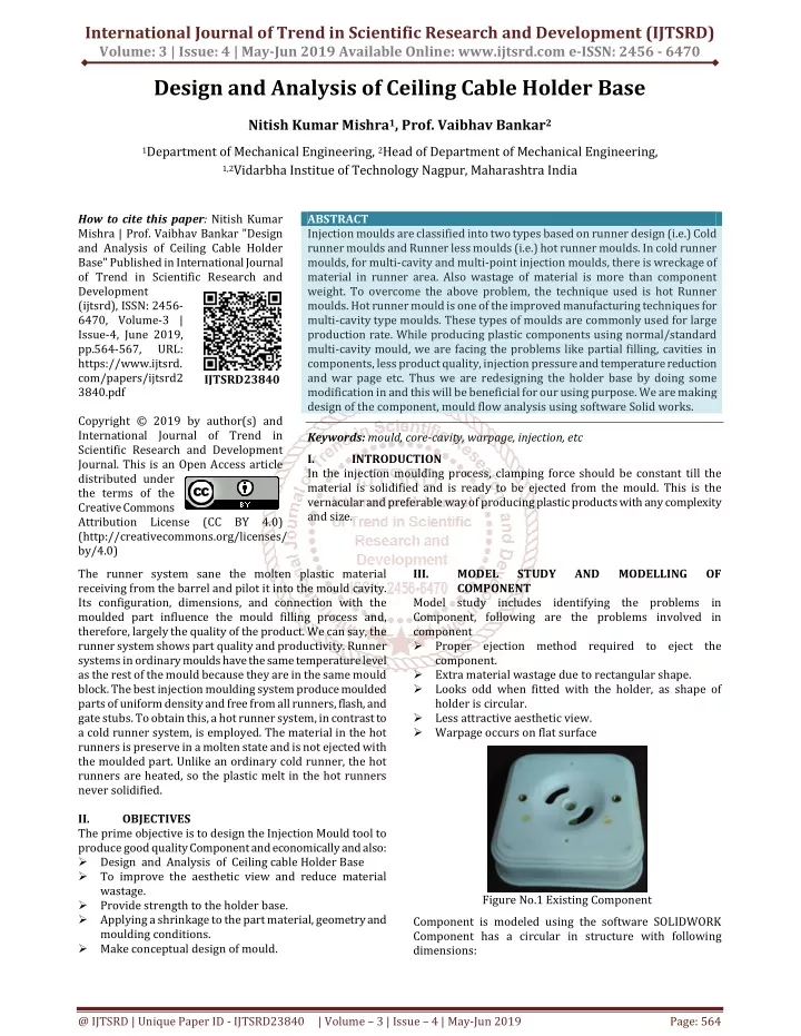
International Journal of Trend in Scientific Research and Development (IJTSRD) Volume: 3 | Issue: 4 | May-Jun 2019 Available Online: www.ijtsrd.com e-ISSN: 2456 - 6470 Design and Analysis of Ceiling Cable Holder Base Nitish Kumar Mishra1, Prof. Vaibhav Bankar2 1Department of Mechanical Engineering, 2Head of Department of Mechanical Engineering, 1,2Vidarbha Institue of Technology Nagpur, Maharashtra India How to cite this paper: Nitish Kumar Mishra | Prof. Vaibhav Bankar "Design and Analysis of Ceiling Cable Holder Base" Published in International Journal of Trend in Scientific Research and Development (ijtsrd), ISSN: 2456- 6470, Volume-3 | Issue-4, June 2019, pp.564-567, URL: https://www.ijtsrd. com/papers/ijtsrd2 3840.pdf Copyright © 2019 by author(s) and International Journal of Trend in Scientific Research and Development Journal. This is an Open Access article distributed under the terms of the Creative Commons Attribution License (CC BY 4.0) (http://creativecommons.org/licenses/ by/4.0) The runner system sane the molten plastic material receiving from the barrel and pilot it into the mould cavity. Its configuration, dimensions, and connection with the moulded part influence the mould filling process and, therefore, largely the quality of the product. We can say, the runner system shows part quality and productivity. Runner systems in ordinary moulds have the same temperature level as the rest of the mould because they are in the same mould block. The best injection moulding system produce moulded parts of uniform density and free from all runners, flash, and gate stubs. To obtain this, a hot runner system, in contrast to a cold runner system, is employed. The material in the hot runners is preserve in a molten state and is not ejected with the moulded part. Unlike an ordinary cold runner, the hot runners are heated, so the plastic melt in the hot runners never solidified. II. OBJECTIVES The prime objective is to design the Injection Mould tool to produce good quality Component and economically and also: ?Design and Analysis of Ceiling cable Holder Base ?To improve the aesthetic view and reduce material wastage. ?Provide strength to the holder base. ?Applying a shrinkage to the part material, geometry and moulding conditions. ?Make conceptual design of mould. ABSTRACT Injection moulds are classified into two types based on runner design (i.e.) Cold runner moulds and Runner less moulds (i.e.) hot runner moulds. In cold runner moulds, for multi-cavity and multi-point injection moulds, there is wreckage of material in runner area. Also wastage of material is more than component weight. To overcome the above problem, the technique used is hot Runner moulds. Hot runner mould is one of the improved manufacturing techniques for multi-cavity type moulds. These types of moulds are commonly used for large production rate. While producing plastic components using normal/standard multi-cavity mould, we are facing the problems like partial filling, cavities in components, less product quality, injection pressure and temperature reduction and war page etc. Thus we are redesigning the holder base by doing some modification in and this will be beneficial for our using purpose. We are making design of the component, mould flow analysis using software Solid works. Keywords: mould, core-cavity, warpage, injection, etc I. INTRODUCTION In the injection moulding process, clamping force should be constant till the material is solidified and is ready to be ejected from the mould. This is the vernacular and preferable way of producing plastic products with any complexity and size. IJTSRD23840 MODEL COMPONENT III. STUDY AND MODELLING OF Model study includes identifying the problems in Component, following are the problems involved in component ?Proper ejection method required to eject the component. ?Extra material wastage due to rectangular shape. ?Looks odd when fitted with the holder, as shape of holder is circular. ?Less attractive aesthetic view. ?Warpage occurs on flat surface Figure No.1 Existing Component Component is modeled using the software SOLIDWORK Component has a circular in structure with following dimensions: @ IJTSRD | Unique Paper ID - IJTSRD23840 | Volume – 3 | Issue – 4 | May-Jun 2019 Page: 564
International Journal of Trend in Scientific Research and Development (IJTSRD) @ www.ijtsrd.com eISSN: 2456-6470 Data from CAD model Material = Polypropylene Mass = 10 grams QB = 546 KJ/Kg Density = 0.9 kg/dm3 Moulding Temp = 250 0C Calculation of Number Cavities Based on:- 1.Shot Capacity Ns= Where, Ns: Number of cavities based on shot capacity M: - Mass of component. W: - shot capacity for polymer Sv: - Swept Volume C: - Constant ρ :- Density of material. Sv= 100 cm2 W 0.95 Figure No.2 Dimension of Holder Base. Other details of model are given below:- ?Component name: Holder Base ?Component material: PP (polypropylene) ?Shrinkage: 1.5 ?Moulding type: Four Cavity injection mould tool W = 59.85 gm. Ns =5.08 5 2.Plasticizing Capacity Where, Np:- Number of Cavities Based on Plasticizing Capacity. Tc = cycle time M = Mass = 10 gram. Ps :- Plasticizing Capacity of Machine = 6.1 kg/hr QA- Total Heat Content of Polystyrene. QB- Total Heat Content of Material. P= Figure No.3 3D model of Knob. IV. This section describes the design aspects and other Considerations involved in designing the mould to manufacture holder Base. Three design concepts are considered in designing of the mould including: i. Three-plate mould (Concept 1) has two parting line with single cavity. ii.Two-plate mould (Concept 2) has one parting line with many cavities with gating and ejection system. iii. Two-plate mould (Concept 3) has one parting line with single cavity without gating system. For designing the mould second concept had been applied. First, the mould was designed based on the flat dimension of the plastic injection machine used. Mostly, core and cavity extraction was done on the basis of the criticality of the component, after core-cavity extraction from specified modeling software, mold base also modeled on the same software, at last core cavity inserts are assembled into the mold base. Design calculation Numeric calculation to be carried out to predict the weight of the component, Shot Capacity, Plasticizing Capacity, Clamping Capacity, on which machine mold to be loaded, plasticizing and shot capacity of the machine, and cooling parameters like inlet and outlet temperature effect, quantity of water to be circulate. These results are tally with the simulation results during moulding. DESIGN OF MOULD P= P = 15.27 Kg/hr. Tc= Tc= Tc = 2.357 second. Np= Np = 4.37 4 Determination of number of cavity From the above calculation of component and its shape and size 4 cavity moulds is preferred. V. MOULD FLOW ANALYSIS It is required to do the mould flow analysis for the particular component to know the proper filling and any other defects coming during the filling process of the component. To locate the proper gatting system and melt temperature of the material in which injection process takes place. Following are some images of analysis. @ IJTSRD | Unique Paper ID - IJTSRD23840 | Volume – 3 | Issue – 4 | May-Jun 2019 Page: 565
International Journal of Trend in Scientific Research and Development (IJTSRD) @ www.ijtsrd.com eISSN: 2456-6470 Graph No. 2 Y Direct. Clamping Force Vs Time Figure No.4 Analysis of Filling Time VI. Tool assembly is done in modeling software, includes the positioning of extracted core and cavity inserts into the mould base, after assembly 3D models are converted into the 2D drawings for manufacturing process. TOOL ASSEMBLY Figure No.5 Analysis of Cooling Time Figure No.8 Core Cavity Extraction Figure No.6 Analysis of Temperature at the End of Fill Figure No. 9 Assembly of mould tool Figure No.7 Analysis of Ease of Fill Figure No.10 Drafting of Mould Assembly Graph No. 1 X Direct. Clamping Force Vs Time Figure No.11 Drafting of core insert @ IJTSRD | Unique Paper ID - IJTSRD23840 | Volume – 3 | Issue – 4 | May-Jun 2019 Page: 566
International Journal of Trend in Scientific Research and Development (IJTSRD) @ www.ijtsrd.com eISSN: 2456-6470 [5]S. Karthikeyan, S. Jayabal, S. kalyanasundaram, C Boopathi, “Influence of Cooling Channel Position and Form on Polymer Solidification and Temperature in Injection Molding Die”,International Journal For Research In Applied Science & Engineering Technology (IJRASET), Volume 3 Issue III, March 2015. VII. In this project, we carried out the Design and Analysis of Ceiling Cable Holder Base. The complete injection mould tool is designed for fabricating holder base by using solid work. The plastic flow analysis is carried out using solid work. All the results viz. fill time, temperature at the end of fill, weld lines, air traps, Ease of fill prediction are analysed and also we have design the mould tool assembly for holder base by considering standard design consideration and it has not shown any error in the mould flow analysis. VIII. REFERENCES [1]R. Folgado, P. Pec-as n, E. Henriques, “Life cycle cost for technology selection: manufacturing of injection moulds”, International Journal of Production Economics Volume 128 (2010). CONCLUSION [6]Book on Injection mould design by R.G.W.PYE [7]B. Iftekhar Hussain, Mir Safiulla, Mohamed Ali, G. Suresh, "Injection Mould Tool Design of Power Box Side Panel", International Journal of Innovative Research in Science, Engineering and Technology, Vol. 3, Issue 2, February 2014. A Case study in the [8]NikMizamzulMehat, Shahrul Kamaruddin, and Abdul Rahim Othman, "Modeling and Analysis of Injection Moulding Process Parameters for Plastic Gear Industry Application”, Hindawi Publishing Corporation ISRN Industrial Engineering Volume 2013, Article ID 869736. [2]M Shoeab Sheikh Dr. Prashant Sharma “Design Analysis For Components Of Pneumatic Injection Moulding Machine Using Pro-E” International Journal Of Innovations In Engineering Research And Technology [IJIERT] Volume 2, Issue 7, July-2015. [9]Jithin k1, Kannakumar k2, "Process Parameter Optimization of Injection Mold Using Concurrent Approach”, IJISET - International Journal of Innovative Science, Engineering & Technology, Vol. 3 Issue 12, December 2016. [3]Korrapati Surendra Babu Sk. Muneer Basha Dr. Ch. Sreedhar “Design And Simulation Of Plastic Injection Molding Process By Using Ansys”, Anveshana’s International Journal Of Research In Engineering And Applied Sciences, Volume 1, Issue 11 Nov-2016. [10]Vijaykumar Vilas Andhalka, Dr. S. R. Dulange, "Injection molding methods design, optimization, Simulation of plastic flow reducer part by mold flow analysis”, International Research Journal of Engineering and Technology (IRJET) Volume: 04 Issue: 06 | June -2017. [4]S. Kamaruddin, Zahid A. Khan and S. H. Foong, “Application of Taguchi Method in the Optimization of Injection Moulding Parameters for Manufacturing Products from Plastic Blend”, IACSIT International Journal of Engineering and Technology, Vol.2, No.6, December 2010. [11]Bown, J., “Injection Moulding of Plastic Components”, McGraw-Hill. @ IJTSRD | Unique Paper ID - IJTSRD23840 | Volume – 3 | Issue – 4 | May-Jun 2019 Page: 567