Download

1 / 6
60 likes | 70 Views
This paper describes a dynamic model of a SOFC fuel cell, which can be used in transient stability studies. The model is applied to a distributed utility grid that uses a fuel cell and a gas turbine as distributed generators DGs . Transient stability of the system is investigated for different DGs power outputs using a software developed based on the commercial Power System Tool Box and SIMULINK in MATLAB. A method for interfacing the fuel cell to the grid is presented. Transient stability is enhanced through a control design of the firing angle of the fuel cell inverter for the couple of well known applications are discussed. Rameez Hassan Pala "Operation and Control of Grid-Connected Fuel Cell System" Published in International Journal of Trend in Scientific Research and Development (ijtsrd), ISSN: 2456-6470, Volume-3 | Issue-2 , February 2019, URL: https://www.ijtsrd.com/papers/ijtsrd20317.pdf Paper URL: https://www.ijtsrd.com/engineering/electrical-engineering/20317/operation-and-control-of-grid-connected-fuel-cell-system/rameez-hassan-pala<br>

E N D
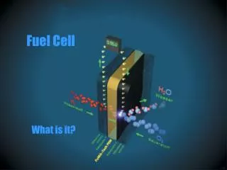
International Journal of Trend in Scientific Research and Development (IJTSRD) Volume: 3 | Issue: 2 | Jan-Feb 2019 Available Online: www.ijtsrd.com e-ISSN: 2456 - 6470 Operation and Control of Grid-Connected Fuel Cell System Rameez Hassan Pala M.Tech Scholar, Electrical Engineering Department, Yamuna Institute of Engineering & Technology, Yamunanagar, Haryana, India ABSTRACT This paper describes a dynamic model of a SOFC fuel cell, which can be used in transient stability studies. The model is applied to a distributed utility grid that uses a fuel cell and a gas turbine as distributed generators (DGs). Transient stability of the system is investigated for different DGs power outputs using a software developed based on the commercial Power System Tool Box and SIMULINK in MATLAB. A method for interfacing the fuel cell to the grid is presented. Transient stability is enhanced through a control design of the firing angle of the fuel cell inverter for the couple of well-known applications are discussed. KEYWORDS: Distributed generation; Renewable energy sources; Fuel cell systems; Power-conditioning units; dc/dc converters; dc/ac inverters I. INTRODUCTION DISTRIBUTED generation (DG) is expected to play a major role in future power generation systems. Most likely, Fuel Cells and microturbines will be the dominant DGs. Particularly, Fuel Cells are attractive because they are modular, efficient, and environmentally friendly. These DGs are dynamic devices and when connected to the power system they will affect its dynamic behavior. Hence, several researchers are working to develop dynamic models for these components. Fuel Cells produce DC voltage outputs, and they are connected to the power electric networks through power conditioning units such as DC/AC inverters. Most of the published papers on Fuel Cell modeling concentrate on chemical aspects, and very few have addressed the topic of grid interface [1], [2], [3], [7]. The type of the Fuel Cell plays an important role in finding a suitable dynamic model as the internal chemical reactions vary. Two types of Fuel Cells can be used as power plants SOFC (Solid Oxide Fuel Cell) and MCFC (Molten Carbonate Fuel Cells) [3]. This paper develops a generic dynamic model for a grid- connected fuel-cell plant. The model is defined by a small number of parameters and is suitable for planning studies. The steady state power generation characteristics of the plant are derived and analyzed. Two major loops for The SOFC systems have been proposed for electric utility power generation in both large central power plants and distributed generation stations [8], [9]. Understanding the transient behavior of SOFCs is important for control of stationary utility generators during power system faults, surges and switching. The model derived is based on the main chemical equations and type of the fuel cell. It is developed in the Laplace domain and transient simulation is done using a software developed based on the MATLAB package. A technique to interface power plant fuel cell to power network is introduced. The steady state characteristics of the plant are derived and analyzed. A test system which consists of two DGs, a fuel cell and a gas turbine, connected to the grid is investigated. Transient stability is analyzed based on the penetration level of each DG. In addition, a controller is designed for the fuel cell to enhance transient stability of the system. II. SOFCFUEL-CELLGENERATOR A fuel cell is an electrochemical device that converts the chemical energy of the fuel (hydrogen) into electrical energy. It is centered on a chemical reaction between the fuel and the oxidant (generally oxygen) to produce electricity where water and heat are byproducts. This conversion of the fuel into energy takes place without combustion. Generally, efficiency of the fuel cells ranges from 40-60% and can be improved to 80-90% in cogeneration applications. The waste heat produced by the lower temperature cells is undesirable since it cannot be used for any application and thus limits the efficiency of the system. The higher temperature fuel cells have higher efficiency since the heat produced can be used for heating purposes. 2.1.1 Operating Principle. The structure and the functioning of a fuel cell is similar to that of a battery except that the fuel can be continuously fed into the cell. The cell consists of two electrodes, anode (negative electrode) and cathode (positive electrode) separated by an electrolyte. Fuel is fed into the anode where electrochemical oxidation takes place and the oxidant is fed into the cathode where electrochemical reduction takes place to produce electric current and water is the primary product of the cell reaction. Figure 1 shows the flows of reactants in a simplified fuel cell. The hydrogen which enters the anode side is broken into hydrogen ions and electrons with the help of the catalyst. Incase of lower temperature cells like the PEMFC and the PAFC, the hydrogen ions move through the electrolyte and the electrons flow through the external circuit. The oxygen which enters through the cathode side combines with these hydrogen ions and electrons to form water as shown in the above figure. As this water is removed, more ions are passed through the electrolyte to continue the reaction which results in further power production. @ IJTSRD | Unique Reference Paper ID - IJTSRD20317 | Volume – 3 | Issue – 2 | Jan-Feb 2019 Page: 159
International Journal of Trend in Scientific Research and Development (IJTSRD) @ www.ijtsrd.com eISSN: 2456-6470 Fig.2. Components of Fuel cell stack. G - products G = f f Fig.2.1.Schematic of an individual fuel cell. ∆ G reactance In the SOFC, it is not the hydrogen ions which move through the electrolyte, but the oxygen radicals. In case of MCFC, carbon dioxide combines with the oxygen and electrons to form carbonate ions, which are transmitted through the electrolyte. Fuel cells are classified based on the type of electrolyte used. A solid polymer membrane electrolyte is fitted between two platinum catalyzed porous electrodes for PEM fuel cells. MCFCs have a liquid lithium-potassium or lithium-sodium based electrolyte while SOFCs employ a solid yittra-stablized zirconia ceramic electrolyte. The catalyst used for SOFC and MCFC are perovsikites and nickel, respectively, the cost of which is comparatively lower than that used for PEMFC. The typical anode and cathode reactions for a hydrogen fuel cell are given by Equations (1) and (2), respectively. − ++ → e H H 2 2 2 1 → + + (3) f These quantities can be expressed in their ‘per mole’ form to make the comparisons easier. They are indicated by – over the lower case letter (gf ) which is given by Equation (4). g products g g − = ∆ reactance f f f (4) For the hydrogen fuel cell, two electrons pass through the external circuit for each water molecule produced and each molecule of hydrogen used, as given in Equation (1). In a lossless system, electrical work done is equal to the change in Gibbs free energy. Further, electrical work done to move a charge of 2F (to move two electrons) for a voltage of E is given by Equation (5) . Electrical work done = -2FE joules Therefore E can be written as shown in Equation (6). This voltage is the open circuit voltage of the fuel cell . g E 2 Consider a general reaction given as jJ + kK → mM where j moles of J and k moles of K react with each other to produce m moles of M. These reactants and products have an activity (a) associated with them. This activity is the ratio of the partial pressure of the gas and the standard pressure. Hence Gibbs free energy can be written as shown in the Equation (7) . ∆gf0 is the change in the Gibbs free energy of formation at standard pressure. − ∆ = ∆ f f a (5) (1) ∆ + − 2 2 O H e H O f 2 2 = − 2 (2) F (6) An individual fuel cell produces less than a volt of electric potential. A large number of cells are stacked on top of each other and connected in series (with bipolar connects) to produce higher voltages. Figure 2 shows cell stacks which consists of repeating units, each comprising an anode, cathode, electrolyte and a bipolar separator plate. The number of cells depends on the desired power output. 2.1.1. Fuel Cell Voltage and Nernst Equation. The chemical energy of the fuel cell is defined by enthalpy of formation and Gibbs free energy. Gibbs free energy is the energy available to do external work which involves moving electrons around an external circuit. Enthalpy of formation is the sum of Gibbs free energy and the energy connected with entropy. In fuel cells, change in Gibbs free energy of formation (∆Gf) is considered, as this change is responsible for the energy released. This change is the difference between the free energy of the products and the reactants, as shown in Equation (3). j j k k a . a 0 ln g g RT m M (7) Equation (7) can be applied to a typical hydrogen fuel cell reaction, where the reactants are hydrogen and oxygen and the product is water. Since activity is the pressure of the gas to its standard pressure, activity can be replaced by pressure in Equation (7). Further, the standard pressure is considered to beunity. Hence, Equations (6) and (7) can be combined together to obtain an equation for voltage as shown in Equation (8), also known as the Nernst equation . / 1 02 2 2. p p p H ln RT 0 = − ∆ + / 2 E g F f 20 H (8) @ IJTSRD | Unique Reference Paper ID - IJTSRD20317 | Volume – 3 | Issue – 2 | Jan-Feb 2019 Page: 160
International Journal of Trend in Scientific Research and Development (IJTSRD) @ www.ijtsrd.com eISSN: 2456-6470 Types of Fuel Cells. thereby reducing the efficiency. Higher temperature fuel cells do not require an external reformer; its high temperature allows direct conversion of natural gas to hydrogen. High temperature requires stringent materials which increases the cost of the fuel cells. Hence, researchers are working to combine the benefits of the PEMFC and the PAFC to obtain intermediate temperature cells, often referred to as high temperature PEM. Table1. Summary of characteristics of fuel cell types Criteria PEMFC PAFC Operating Temperat ure Operating Pressure 3-250 kW 200 kW Efficiency 35-40% 35-40% 2.1.2. Fuel cells are classified according to the type of electrolyte used. There are various fuel cell types at different stages of development. The various types of fuel cells in the increasing order of their operating temperature are: ?Proton exchange membrane fuel cell (PEMFC-175oF) ?Phosphoric acid fuel cell (PAFC-400o F) ?Molten carbonate fuel cell (MCFC-1250o F) ?Solid oxide fuel cell (SOFC-1800o F) Each of these fuel cell types differ in the electrolyte and fuel used, operating temperature and pressure, construction materials, power density and efficiency. Table 1 gives a basic summary of the characteristics and requirements of the fuel cell types mentioned above. The most important component of a fuel cell is the fuel processor and the reformer since hydrogen is not readily available. Fossil fuels such as gasoline, natural gas and coal gases need to be processed and reformed to obtain enriched hydrogen. Natural gas is the most easily available fuel source. Bio-fuels can also be used as a source to obtain hydrogen. Biological methods such as photosynthesis and fermentation can be used to produce hydrogen. Though there are different methods to produce hydrogen, a proper and feasible method which can be commercialized is not yet available. Storage of hydrogen is an important aspect of the fuel cell systems because the fuel has to be readily available for continuous supply of electric power. Sometimes, electrical energy is used to divide water into hydrogen and oxygen with the help of electrolysers during times of high supply and low demand. Fuel cells have to be compact and portable for mobile applications; hence storage of hydrogen is essential for such applications. Hydrogen needs to be handled with great care because it is a highly volatile and flammable gas. It has a high leak rate due to which the gas tends to escape through small orifices, faster than the other gases. Hence storage of hydrogen plays a key role in the fuel cell systems. Hydrogen can be stored as a compressed gas in pressurized cylinders and is the most common method of storage. This method is simple, indefinite storage time and there are no purity limits on the gas. It is used in places where demand for hydrogen is variable and not high. The next method of storage is as a cryogenic liquid at a temperature of 22K. This method is used for storing large quantities of hydrogen. Storing hydrogen at low temperatures is not a preferred method due to the safety problems associated with it. Frostbite is a major concern for this method of storage. Hydrogen can also be stored as a metal hydride. This method basically consists of a reversible reaction between a metal and hydrogen. Hydrogen is supplied to the metal alloy at slightly above atmospheric pressure to form the metal hydride. The reaction is mildly exothermic and normal air cooling would be sufficient for the reaction. Once the metal has reacted with hydrogen, it is stored in a vessel and sealed. Carbon monoxide can be used as a fuel for SOFC and MCFC because it can be internally converted to hydrogen whereas the PEMFC should be completely free from it. Carbon monoxide has high affinity for anode catalyst (especially platinum) and it prevents the flow of fuel in the PEMFC. Ammonia is a poison for all the fuel cell types due to its adverse effects on the cell life except for SOFC, where it can be internally reformed. Lower-temperature fuel cells require an external reformer to obtain the hydrogen rich fuel, thus increasing the cost and MCFC SOFC ~ 400o F ~ 1250o F ~ 1800o F < 210o F 1-5 atm 1-8 atm 1-3 atm 1-13 atm 100- 250Kw- 10MW 50-55% H2, CO, CH4 1kW- 10MW 45-50% H2,CO,CH 4, NH3 Size Range Fuel H2 H2 CO,NH3, Cl2,S2 CO,NH3, Cl2,S2 Poison Cl2, S2 S2 Charge Carrier Constructi on Material Cooling Medium H+ H+ CO32- O2- Graphit e carbon Graphit e carbon Boiling water Ni and stainles s steel Excess air Ceramics and Metals Excess air Water SOLID OXIDE FUEL CELL (SOFC) The SOFC is a high-temperature operating fuel cell which has high potential in stationary applications. The efficiency of SOFC is in the range of 45-50% and when integrated with a gas turbine, it reaches a high efficiency of 70-75%. It is a solid-state device that uses an oxide ion-conducting non- porous ceramic material as an electrolyte. Since the electrolyte is a solid, the cells do not have to be constructed in the plate-like configuration typical of other fuel cell types. Corrosion is less compared to MCFC and no water management problems as in PEMFCs due to the solid electrolyte. High temperature operation removes the need for a precious-metal catalyst, thereby reducing the cost. It also allows SOFCs to reform fuels internally, which enables the use of a variety of fuels and reduces the cost associated with adding a reformer to the system. Two different geometries which are being developed are tubular and planar. Tubular designs are more costly and advanced compared to the planar designs and is closer to commercialization. The electrolyte used is a ceramic oxide (yttria stabilized zirconia). The anode used is nickel-zirconia cermet and the cathode is a strontium doped lanthanum manganite. The use of ceramic materials increases the cost of SOFCs. High operating temperature requires stringent materials to be used which further drives up the cost. Research is being carried out to reduce the operating temperature and use less stringent materials. Reduction of temperature improves the starting time, cheaper materials can be used, durability and robustness can be increased. Intermediate-temperature SOFCs cannot be used for all applications. Higher temperature is required for fuel cell micro-turbine hybrid systems. However, for smaller systems intermediate temperature SOFCs would be ideal. @ IJTSRD | Unique Reference Paper ID - IJTSRD20317 | Volume – 3 | Issue – 2 | Jan-Feb 2019 Page: 161
International Journal of Trend in Scientific Research and Development (IJTSRD) @ www.ijtsrd.com eISSN: 2456-6470 III. The fuel cell stack is connected to the DC-DC converter to boost the DC voltage to connect it to the utility grid via the DC-AC inverter. The fuel cell, DC-DC converter and DC-AC inverter are modeled in MATLAB/Simulink R2015a. Figure 3 shows the block diagram representation of the fuel cell system connected to the utility grid through the transformer and the coupling reactance. SIMULATIONMODELLINGANDRESULTS DC-DC Converter Model. The input to the converter is the fuel cell stack voltage. A step change in the equivalent load resistance is considered. The higher the value of capacitance, the smoother the output voltage. A filter inductor connected in series with the load resistance causes the output current to be smooth. Figure 5 shows the dynamic model of the DC-DC buck-boost converter. Figure 3 Grid connected fuel cell system. The following assumptions have been made in this system: ?The three phase transmission line has been considered to be ideal. ? Reactive power is assumed to be zero (Q). ?Switching losses of the inverter are neglected. The following constraints have been made for simulating the fuel cell power system: The Line-line rms voltage across the inverter constraint is given by Inequality (1). The relationship between the inverter and the transformer voltage is expressed by Equation (9). V VLLrmsi≤ The maximum fuel cell stack power is limited to 400 kW and it loses stability for any reference power beyond this limit. Higher reference power can be commanded by either increasing the number of cells, increasing the standard potential or by decreasing the internal resistance of the fuel cell. The simulations corresponding to the breakdown of the fuel cell can be seen in the results section (Figure 4). The maximum stack power is given by Inequality (10). kW Pfc 400 When the reactive power is considered to be zero, the power flow equation (Equation 9 in section 3.2.1.) is reduced to Equation (11). ) cos( i LLrmsi V φ = SOFC Model. The ac real power injection into the utility grid is considered to be the reference power for the fuel cell. The stack voltage and the reference power are used to determine the reference current which in turn is used to determine the fuel cell stack current. The fuel flow is proportional to the stack current. The partial pressure of hydrogen, oxygen and water are determined using the flow rates of hydrogen and oxygen. The stack voltage is based on the Nernst Equation which depends on the stack current and the partial pressures of the gases. Figure 4.2 shows the mathematical dynamic model of SOFC. Figure 5 Simulink model of SOFC in MATLAB. DC-AC Inverter Model. The input to the three phase inverter is the output voltage of the DC-DC converter. The output voltage of the inverter is a PWM voltage with harmonics which are filtered with an LC filter. The output of the inverter is connected to the utility grid through transmission network. Figure 6 shows the fuel cell system connection to the utility grid through the inverter. 0 2 (9) max≤ (10) Figure 6 Fuel cell and three phase inverter model in MATLAB. The main components required for the inverter control is power regulator and current regulator. This work employs the d-q axis control. The power regulator senses the grid voltage and current. It is basically a PI regulator and produces the idref and iqref current. The idref and iqref current acts as input to the current regulator. Fig. 7 shows the MATLAB/Simulink model of the power regulator. The current regulator gets input from the power regulator. The d-axis reference current and q-axis reference current from the power regulators is fed to current regulator. In current regulator a PI controllers are used. The actual value of d-axis current and q-axis current is compared with the reference values. The error is input to PI controller, which LLrmsiV (11) @ IJTSRD | Unique Reference Paper ID - IJTSRD20317 | Volume – 3 | Issue – 2 | Jan-Feb 2019 Page: 162
International Journal of Trend in Scientific Research and Development (IJTSRD) @ www.ijtsrd.com eISSN: 2456-6470 produces d-q-0 values of current. Then d-q-0 components are converted in to a-b-c components. With the help of pulse generator, this signal is converted in to pulses and these pulses then fed to the inverter gate circuit. SIMULATION RESULTS The MATLAB/Simulink model of fuel cell connected with the grid is subjected with two perturbations. These are: ?Sag in the grid voltage between time 2.5 sec to 3 sec. ?Change in load at 4 sec. These two cases will be discussed in the following sub sections. Sag in grid voltage between 2.5 sec. to 3sec. For analyzing the grid connected fuel cell system the system is subjected with different perturbations. One of these is sag in the grid voltage. Practically the sag is due to sudden increase in load or due to tripping of any generating station. The voltage dip or sag can affect the systemin harmful manner, so it has to be treated accordingly. In this simulation, we have subjected the sag in the grid voltage by changing the grid voltage between time 2.5 sec. to 3 sec. The waveform is shown in figure 8. Figure 11 DC output current of fuel cell. IV. A dynamic model of the solid oxide fuel cell (SOFC) was developed in MATLAB 2015 Ra. A DC-DC buck-boost converter topology and its closed loop control feedback system have been built. A three phase inverter has been modeled and connected between the SOFC-DC-DC system on the one side and the utility grid. A control strategy for the inverter switching signals has been discussed and modeled successfully. The fuel cell, the converter and the inverter characteristics were obtained for a reference real power and reactive power. The response of the fuel cell stack power is compared with two perturbations are applied to the system. One at 2.5 sec. with voltage sag in the grid voltage and other at 4 sec. with load change with both active and reactive power requirement changed. The interconnection of the fuel cell with the converter boosts the stack voltages and also regulates it for continuous current. The fuel cell stack voltage drops to zero for discontinuous current and the system shuts down. The fuel cell unit shuts off for real power above the maximum limit. The inverter control scheme uses a decoupled PQ control strategy to control the phase angle of the inverter and the voltage across the load. The characteristics for the system have been obtained. The grid and inverter power waveforms have been plotted. The L-L rms voltage measured from the system is compared with the value obtained from the reactive control. The measured voltage oscillates with the average value being equal to that obtained from the control. REFERENCES [1]Caisheng and M.hashem, “Power management of a standalone Wind/Photovoltaiv/Fuell Cell Energy System”, IEEE Trans. On energy conversion, Vol.23, No.3, 2008, PP 957-967. CONCLUSIONS Figure 8. Sag in grid voltage waveform Figure 9 Three phase voltage waveform. Figure 9 shows the waveform of the three phase grid voltage. The change in the three phase grid voltage is visible in the rectangular block in the figure 9. As the fuel cell system is connected to the grid there is almost negligible change in the three phase grid voltage. [2]Roy Subhajit, Saha Sanjoy Kumar, 2015. “Implementation of Model to Analyse the Performance of Microturbine as a Dispersed Generator in Micro Grid”, International Journal of Engineering Research & Technology, vol-04, iss-2, February, pp-852-856. [3]P. R. Pathapati, X. Xue, and J. Tang, “A New Dynamic Model for Predicting Transient Phenomena in a PEM Fuel Cell System,” Renewable Energy, vol. 30, Issue 1, pp. 1-22, January 2005. [4]C. Wang, and M. H. Nehrir, “Dynamic Models and Model Validation for a PEM Fuel Cells Using Electrical Circuits,” IEEE Trans. Energy Conversion, vol. 20, Issue 2, pp. 442-451, June 2005. Figure 10 DC output voltage of fuel cell. The fuel cell generates DC voltage and figure 10 shows the generated voltage of the fuel cell system. From the figure it is concluded that the output voltage of the fuel cell system is independent of the sag and load variations. The simulation shows that output voltage remains at 400 V level all the time during the simulation. [5]M. J. Grieve, and K. Rajashekara, “PEM-SOFC hybrid power generation systems”, US Patent 7968237 B2, Jun. 28, 2011. [6] S.R. Oh, J. Sun, H. Dobbs, and J. King, “Model Predictive Control for Power and Thermal Management of an Integrated Solid Oxide Fuel Cell and Turbocharger @ IJTSRD | Unique Reference Paper ID - IJTSRD20317 | Volume – 3 | Issue – 2 | Jan-Feb 2019 Page: 163
International Journal of Trend in Scientific Research and Development (IJTSRD) @ www.ijtsrd.com eISSN: 2456-6470 [17]Nguyen QM. Ceramic Fuel Cells. J. Am. Ceram. Soc. 1993;76(3):563–88. System,” IEEE Transactions on Control Systems Technology, vol.22, no.3, pp.911-920, 2014. [7]E. [18]Brawn R. Report from the Solar Energy Laboratory. University of Wisconsin-Madison, WI. February 2015 (http://sel@sel.me.wisc.edu/). Achenbach, dependent Simulation of a Planar SOFC Stack,” J. Power Sources, vol. 49, Issue 1-3, pp. 333-348, April 1994. “Three-dimensional and Time- [8]K. Sedghisigarchi, and A. Feliachi, “Dynamic and Transient Analysis of Power Distribution Systems with Fuel Cell-Part I: Fuel-Cell Dynamic Model,” IEEE Trans. Energy Conversion, vol. 19, Issue 2, pp. 423-428, June 2004. [19]Mc Evoy A. J. Laboratoire de Photonique et des Interfaces. Ecole Polytechnique Fe´derale de Lausanne, Fuel cell technology status and prospects. June 1998. [20]O. Krishan and Sathans, “Design and Techno-Economic Analysis of a HRES in a Rural Village,” Procedia Comput. Sci., 6th International Conference on Smart Computing and Communications, ICSCC 2017, 7-8 December 2017, Kurukshetra, India vol. 125, pp. 321– 328, 2018. [9]C. Wang, and M. H. Nehrir, “A Physically-Based Dynamic Model for Solid Oxide Fuel Cells,” accepted for IEEE Trans. Energy Conversion September 15, 2006. [10]J. Padulles, G. W. Ault, and J. R. McDonald, “An Integrated SOFC Plant Dynamic Model for Power System Simulation,” J. Power Sources, vol. 86, Issue 1-2, pp. 495-500, 2010. [21]O. Krishan and Sathans, “Frequency regulation in a standalone wind-diesel hybrid power system using pitch-angle controller,” in Proceedings of the 10th INDIACom; 2016 3rd International Conference on Computing for Sustainable Global Development, INDIACom 2016, 2016. [11]C. J. Hatziadoniu, A. A. Lobo, F. Pourboghrat, and M. Daneshdoost, “A Simplified Dynamic Model of Grid- Connected Fuel-Cell Generators,” IEEE Trans. Power Delivery, vol. 17, Issue 2, pp. 467-473, April 2002. [22]O. Krishan and Sathans, “Optimum sizing and economical assessment of grid integrated hybrid system for a rural village: A case study,” in 1st IEEE International Conference on Power Electronics, Intelligent Control and Energy Systems, ICPEICES 2016, 2017. [12]S. Stevandic, and J. Jiang, “A Standalone, Reduced-order Model and Control of a Grid-Connected Fuel Cell Power Plant,” IEEE-PES General Meeting, vol. 2, pp. 679-686, July 2003. [13]Z. Miao, M. A. Choudhry, R. L. Klein, and L. Fan, “Study of a Fuel cell Power Plant in Power Distribution System-Part I: Dynamic Model,” IEEE-PES General Meeting, vol. 2, pp. 2220-2225, June 2004. [23]O. Krishan and S. Suhag, “An updated review of energy storage systems: Classification and applications in distributed generation power systems incorporating renewable energy resources,” Int. J. Energy Res., no. October, pp. 1–40, Nov. 2018. [14]Y. Zhu, and K. Tomsovic, “Development of Models for Analyzing the Load-Following Performance of Micro Turbines and Fuel Cells,” Electric Power Syst. Research, vol. 62, Issue 1, pp. 1-11, May 2002. [24]Venturi M, Mohrdieck C, Friedrich J. Mercedes-Benz b- class fuel cell: the world largest hydrogen vehicle fuel cell fleet experience. In: Proceedings of Electric Vehicle Symposium and Exhibition (EVS27), 2013 World. IEEE; 2013 [15]J. Wen, K. M. Smedley, and M. A. Pai, “Load-Following Improvement of Fuel Cells with Fast Transient OCC Inverter,” Proc. IEEE/ASME, Intl. Conf. on Advanced Intelligent Mechatronics, pp. 140-145, July 2005. [25]Ahn Byung Ki, Tae Won Lim. Fuel cell vehicle development at Hyundai-Kia Motors. In: Proceedings of the 1st international forum on strategic technology, IEEE; 2006 [16]Larminie James, Dicks Andrew. Fuel cell explained. 2nd ed. Wiley Inc.; 2003. @ IJTSRD | Unique Reference Paper ID - IJTSRD20317 | Volume – 3 | Issue – 2 | Jan-Feb 2019 Page: 164