Download
1 / 3
30 likes | 49 Views
Distributed energy units cannot be directly integrated into the power grid due to their inherently varying output. An interfacing technology is required. The power electronic interface is used for connecting distributed energy resources to the smart grid. It can also be used in any type of electric vehicles. It does not store energy in its circuitry. It receives power from the distributed energy source and converts it to power at the required voltage and frequency. This paper provides a brief introduction on power electronic interface. Matthew N. O. Sadiku | Adedamola A. Omotoso | Sarhan M. Musa "Power Electronic Interface" Published in International Journal of Trend in Scientific Research and Development (ijtsrd), ISSN: 2456-6470, Volume-4 | Issue-1 , December 2019, URL: https://www.ijtsrd.com/papers/ijtsrd29394.pdf Paper URL: https://www.ijtsrd.com/engineering/electrical-engineering/29394/power-electronic-interface/matthew-n-o-sadiku<br>

E N D
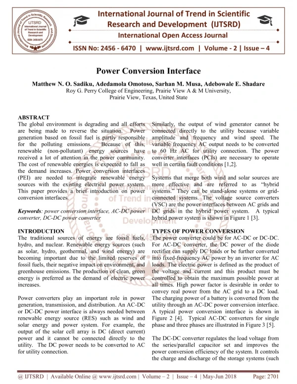
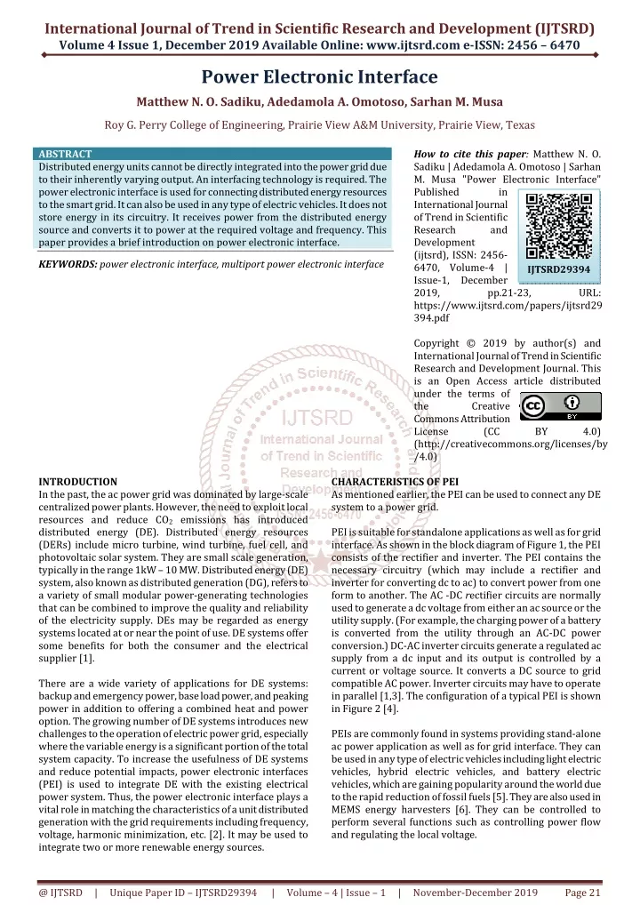
International Journal of Trend in Scientific Research and Development (IJTSRD) Volume 4 Issue 1, December 2019 Available Online: www.ijtsrd.com e-ISSN: 2456 – 6470 Power Electronic Interface Matthew N. O. Sadiku, Adedamola A. Omotoso, Sarhan M. Musa Roy G. Perry College of Engineering, Prairie View A&M University, Prairie View, Texas ABSTRACT Distributed energy units cannot be directly integrated into the power grid due to their inherently varying output. An interfacing technology is required. The power electronic interface is used for connecting distributed energy resources to the smart grid. It can also be used in any type of electric vehicles. It does not store energy in its circuitry. It receives power from the distributed energy source and converts it to power at the required voltage and frequency. This paper provides a brief introduction on power electronic interface. KEYWORDS: power electronic interface, multiport power electronic interface How to cite this paper: Matthew N. O. Sadiku | Adedamola A. Omotoso | Sarhan M. Musa "Power Electronic Interface" Published in International Journal of Trend in Scientific Research and Development (ijtsrd), ISSN: 2456- 6470, Volume-4 | Issue-1, December 2019, pp.21-23, https://www.ijtsrd.com/papers/ijtsrd29 394.pdf Copyright © 2019 by author(s) and International Journal of Trend in Scientific Research and Development Journal. This is an Open Access article distributed under the terms of the Creative Commons Attribution License (CC (http://creativecommons.org/licenses/by /4.0) CHARACTERISTICS OF PEI As mentioned earlier, the PEI can be used to connect any DE system to a power grid. PEI is suitable for standalone applications as well as for grid interface.As shown in the block diagram of Figure 1, the PEI consists of the rectifier and inverter. The PEI contains the necessary circuitry (which may include a rectifier and inverter for converting dc to ac) to convert power from one form to another. The AC -DC rectifier circuits are normally used to generate a dc voltage from either an ac source or the utility supply. (For example, the charging power of a battery is converted from the utility through an AC-DC power conversion.) DC-AC inverter circuits generate a regulated ac supply from a dc input and its output is controlled by a current or voltage source. It converts a DC source to grid compatible AC power. Inverter circuits may have to operate in parallel [1,3]. The configuration of a typical PEI is shown in Figure 2 [4]. PEIs are commonly found in systems providing stand-alone ac power application as well as for grid interface. They can be used in any type of electric vehicles including light electric vehicles, hybrid electric vehicles, and battery electric vehicles, which are gaining popularity around the world due to the rapid reduction of fossil fuels [5]. They are also used in MEMS energy harvesters [6]. They can be controlled to perform several functions such as controlling power flow and regulating the local voltage. IJTSRD29394 URL: BY 4.0) INTRODUCTION In the past, the ac power grid was dominated by large-scale centralized power plants. However, the need to exploit local resources and reduce CO2 emissions has introduced distributed energy (DE). Distributed energy resources (DERs) include micro turbine, wind turbine, fuel cell, and photovoltaic solar system. They are small scale generation, typically in the range 1kW – 10 MW. Distributed energy(DE) system, also known as distributed generation (DG), refers to a variety of small modular power-generating technologies that can be combined to improve the quality and reliability of the electricity supply. DEs may be regarded as energy systems located at or near the point of use. DE systems offer some benefits for both the consumer and the electrical supplier [1]. There are a wide variety of applications for DE systems: backup and emergency power, base load power, and peaking power in addition to offering a combined heat and power option. The growing number of DE systems introduces new challenges to the operation of electric power grid, especially where the variable energy is a significant portion of the total system capacity. To increase the usefulness of DE systems and reduce potential impacts, power electronic interfaces (PEI) is used to integrate DE with the existing electrical power system. Thus, the power electronic interface plays a vital role in matching the characteristics of a unit distributed generation with the grid requirements including frequency, voltage, harmonic minimization, etc. [2]. It may be used to integrate two or more renewable energy sources. @ IJTSRD | Unique Paper ID – IJTSRD29394 | Volume – 4 | Issue – 1 | November-December 2019 Page 21
International Journal of Trend in Scientific Research and Development (IJTSRD) @ www.ijtsrd.com eISSN: 2456-6470 MULTIPORT PEI The idea of multiport power electronic interface (MPEI) refers to interfacing multiple renewable energy sources. It offers direct interface to different sources, storages, and loads. It is dedicated to harvesting and managing renewable energy sources and interacting with utility grid. The block diagram of the MPEI is shown in Figure 3. The ports of MPEI are connected to conventional sources and renewable sources. A five-port MPEI prototype is developed in [7]. As a power interface, MPEI does not store energy in its circuitry. Unified multiple-input PEIs have the advantages of low cost, high power density, and ease of management. MPEIs are used in a variety of applications. For example, they are used for interfacing smart appliances in a smart home . They have been used in managing multiple energy sources and loads in electric vehicles and in the charging process in a charging station [8]. BENEFITS AND CHALLENGES Power electronic interfaces offer unique capabilities over traditional interconnection technologies. They have fast response times. PEIs can respond to events or fault conditions within in the subcycle range. This fast response can enable advanced applications. PEIs can allow for control of voltage and reactive power at the generation source. They can also be used to integrate hybrid systems, which integrate more than one DE technology [1]. Advanced PEIs will allow DE systems to provide increased functionality, increased electric system compatibility, greater electrical flexibility in operations with other DE sources, and energy security. For the customer, benefits include reduced price volatility, greater reliability, and improved power quality. For the energy supplier, benefits include reduced transmission and distribution congestion, improved grid utilization, and the ability of the DE systems to provide ancillary services such as load following, power quality disturbance compensation, and back-up service [1]. However, the addition of PEIs increases costs of the DE infrastructure investment. Power electronics accounts for a significant part of the distributed energy systems cost. In addition to cost and reliability issues, three major challenges facing PEI in DE applications are [9]: ?There is lack of standardization and interoperability among power electronic components. Standardization is needed for the communication interfaces between modules. ?Power electric devices must be modular and scalable. ?Current research efforts focus on power electronic subsystems, not on the DER systems. Designing a suitable, robust, effective PEI to make DE possible can be challenging. CONCLUSION Renewable electricity sources are inherently variable—not intermittent. Power electronic interfaces (PEI) are needed to integrate the sources with the existing electrical power system. Distributed generation system, interfaced to the power grid will become common in the future smart grids due to the advantages mentioned earlier [10]. Development in advanced power electronics technology will improve and accelerate the use of renewable and distributed energy systems and act as an enabler to the success of smart grid implementation.A more thorough discussion on power electronic interfaces is available in [1]. One should also consult IEEE Transactions on Power Electronics. REFERENCES [1]B. Kroposki et al., “ Benefits of power electronic interfaces for distributed energy systems,”IEEE Transactions on Energy Conversion, vol. 25, no. 3, September 2010, pp. 901-908. [2]F. Blaabjerg, Z. Chen, and S. B. Kjaer, “Power electronics as efficient interface in dispersed power generation systems,” IEEE Transactions on Power Electronics, vol. 19, no. 5, September 2004, pp. 1184-1194. [3]S. S. Kannan, K. Vijayakumar, and R. Ramanujam, “Power electronic interface (PEI) based power flow control for micro grid environment – A review,” Proceedings of International Conference on Computation of Power, Energy Information and Communication, 2016, pp. 376-380. [4]J. C. Wu et al., “Novel power electronic interface for grid-connected fuel cell power generation system,” Energy Conversion and Management, vol. 71, 2013, pp. 227-234. [5]O. C. Onar, J. Kobayashi, and A. Khaligh, “A fully directional universal power electronic interface for EV, HEV, and PHEV applications,” IEEE Transactions on Power Electronics, vol. 28, no. 12, December 2013, pp. 5489-5498. [6]B. D. Truong, C. P. Le, and E. Halvorsen, “Analysis of power electronic interface for capacitive MEMS energy harvesters,” Proceedings of the First New Generation of CAS, pp. 173-176. [7]W. Jiang and B. Fahimi, “Multiport power electronic interface—Concept, modeling and design,” IEEE Transactions on Power Electronics, vol. 26, no. 7, July 2011, pp. 1890-1900. [8]P. Shamsi and B. Fahimi, “Modeling of a 3-phase multi- port power electronic interface,” Proceedings of the IEEE International Symposium on Industrial Electronics, 2012, pp. 1035-1039. [9]S. Chakroborty, B, Kramer, and B. Kroposki, “A review of power electronics interfaces for distributed energy systems towards achieving low-cost modular design,” Renewable and Sustainable Energy Reviews, vol. 13, 2009, pp. 232-2335. [10]A. E. Mejia, “Indirect matrix converter as standard power electronic interface,” Doctoral Dissertation, University of Arkansas, December 2014. @ IJTSRD | Unique Paper ID – IJTSRD29394 | Volume – 4 | Issue – 1 | November-December 2019 Page 22
International Journal of Trend in Scientific Research and Development (IJTSRD) @ www.ijtsrd.com eISSN: 2456-6470 Figure 1 DE system and PEI block diagram [1]. Figure 2 A typical PEI circuit [4]. Figure 3 Multiport power electronic interface (MPEI) [6]. @ IJTSRD | Unique Paper ID – IJTSRD29394 | Volume – 4 | Issue – 1 | November-December 2019 Page 23