Download
1 / 1
10 likes | 122 Views
PAMELA - Injection, Extraction and Gantry. Injection

E N D
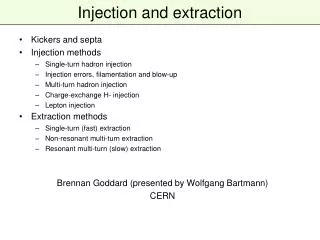
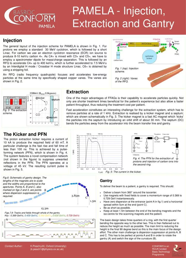
PAMELA - Injection, Extraction and Gantry Injection The general layout of the injection scheme for PAMELA is shown in Fig. 1. For protons we employ a standard 30 MeV cyclotron, which is followed by a short Linac. For carbon we use an electron cyclotron resonance (ECR) ion source to produce 8-10 keV/u carbon 4+. As C4+ is mixed with C3+ and C5+, we have to employ a spectrometer dipole for mass/charge separation. This is followed by an RFQ to accelerate C4+ up to 400 keV/u, which is further accelerated to 7.5 MeV/u by an Interdigital H mode / Crossbar H mode structure Linac. C6+ is obtained by using a stripping foil. An RFQ (radio frequency quadrupole) focuses and accelerates low-energy particles at the same time by specifically shaped copper vanes. The vanes are shown in Fig. 2. Fig. 1 (top): Injection scheme. Fig. 2 (right): Vanes of the RFQ. Extraction One of the major advantages of FFAGs is their capability to accelerate particles quickly. Not only are shorter treatment times beneficial for the patient’s experience but also allow a faster patient throughput, thus reducing the treatment cost per patient. Fast acceleration constitutes an interesting challenge for the extraction system, which has to remove particles at a rate of 1 kHz. Extraction is realised by a kicker magnet and a septum; which are shown schematically in Fig. 3. The kicker magnet is a fast AC magnet which ‘kicks’ the particles into the septum by introducing an orbit shift of about 30 mm. The septum (DC) bends the particles away from the accelerator into the beam transfer line and gantry. Fig. 3: The extraction scheme. The Kicker and PFN The proton extraction kicker requires a current of 10 kA to produce the required field of 60 mT. A particular challenge is the fast rise and fall time of less than 100 ns. This is achieved by a pulse-forming network (PFN), which is shown in Fig. 4. The system features a novel compensation network (not shown in the figure) to suppress unwanted reflections in the PFN. The PFN operates at a voltage of 45 kV. The resulting current pulse is shown in Fig. 5. Fig. 4: The PFN for the extraction of protons and injection of carbon ions into the second ring. Fig. 5: The current in the kicker. Fig.6: Schematic of gantry design. The lengths of the magnets are to scale and the widths are proportional to the apertures. Points A, B and C, also marked on figs 2 and 3, are points where dispersion suppression is required. • Gantry • To deliver the beam to a patient, a gantry is required. This should: • Deliver a beam from 360° around the isocenter. • Use magnets with fixed fields to cover a momentum range of 0.369 to 0.729 GeV instantaneously. • Have zero dispersion at the entrance (point A in fig.1) and a horizontal spread within 5cm at the end (point C). • Be as short as possible. • Keep at least 1.5m between the end of the bending magnets and the iso-centre for the scanning magnets and the patient. The basic design takes three quarters of a ring, with the first quarter bending the opposite way to the other two. This is then flattened out to reduce the height as much as possible. The main limit to reducing the height is the final 90 degree bend so this is the main focus of the design effort. The other main challenge is dispersion suppression at points A, B and C. This has to be perfect at points A and B in order to rotate the gantry (A) and switch the sign of the curvature (B). B 3.85m C 1.5m A 15.3m Figs.7,8: Tracks and fields through whole of the gantry. Key : 0.369 GeV/c, 0.459 GeV/c, 0.549 GeV/c, 0.639 GeV/c, 0.729 GeV/c A B C K.Peach(JAI, Oxford University) (k.peach1@physics.ox.ac.uk)