Download
1 / 38
400 likes | 583 Views
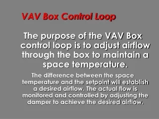
Static Pressure Control Loop. The purpose of the static pressure control loop is to maintain an optimal static pressure in the ductwork.

E N D
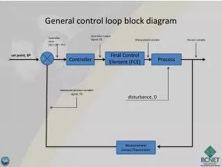
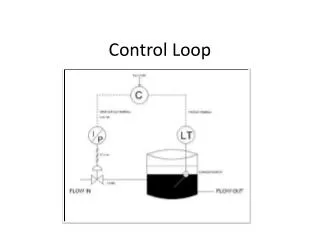
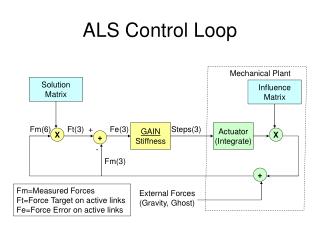
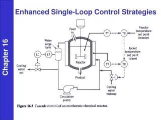
Static Pressure Control Loop • The purpose of the static pressure control loop is to maintain an optimal static pressure in the ductwork. • The control loop senses the static pressure in the ductwork and compares it to a setpoint. The controller sends an output signal to the VSD which controls the fan speed. Adjusting the fan speed impacts the static pressure in the ductwork.
Static Pressure Control Loop Duct Static Temperature DDC Control Calculations Signal to VSD Controller Fan Speed Air flow through ductwork
Static Pressure Control Loop Cooling Coil Air Flow Static Pressure Sensor Variable Speed Drive DDC Controller Tuning Parameters
Static Pressure Control Loop Control Loop Setpoint
Static Pressure Control Loop • Control Loop Setpoint • Selecting the correct setpoint is very important for system performance. • The optimal setpoint cannot be calculated in advance. It must be determined in the field. The current practice of fixing the setpoint wastes a lot of energy.
Static Pressure Control Loop • Control Loop Setpoint • If the setpoint is too low, some boxes will not be able to get enough air to provide comfort. • Some boxes will have their damper 100% open but the actual flow will still be less than the desired flow. These boxes are “starved” and the VAV box will not be able to achieve the space temperature setpoint.
Static Pressure Control Loop • Control Loop Setpoint • If the setpoint is too high, fan energy is wasted. • The higher the static pressure setpoint, the harder the fan must work to maintain the setpoint.
Static Pressure Control Loop • Control Loop Setpoint • If the setpoint is too high, the noise of the system will increase. • If the static pressure setpoint is high, all of the VAV box dampers will only need to open a little bit to achieve the desired airflow. Airflow going through a small opening generates a lot of noise.
Static Pressure Control Loop • Control Loop Setpoint • If the setpoint is too high, VAV box control may go unstable. • With a high static pressure setpoint, the throttling range of the damper to go from minimum flow to maximum flow is decreased. A small control adjustment to damper position has a large effect on airflow. The flow control loop is very sensitive and may cycle, depending on the control loop parameters.
Static Pressure Control Loop • Control Loop Setpoint • During air balancing, use a high setpoint to make sure that none of the boxes are starved.
Static Pressure Control Loop • Control Loop Setpoint • Choosing the optimal setpoint: • 1. Enter a low setpoint so that some of the VAV boxes are starved with damper 100% open • 2. Increase the static pressure setpoint until all of the VAV boxes are in control; damper less than 100% open
Static Pressure Control Loop • Control Loop Setpoint • Static Pressure Reset Energy Saving Strategy: • 1. Every five minutes, check the position of all VAV box dampers. • 2. If the damper which is open the most is more than 90% open, increase the static pressure setpoint by 50 Pascal. • 3. If the damper which is open the most is less than 80% open, decrease the static pressure setpoint by 50 Pascal.
Static Pressure Control Loop • Control Loop Setpoint Fan Speed of 40% Static Pressure Setpoint = 100 Pascal FlowD 400 Damper 100% FlowA 300 FlowD 250 Damper 70% FlowA 250 FlowD 150 Damper 30% FlowA 150 Zone A “Hot” Zone B “Warm” Zone C “Cool” FlowD = Desired Flow FlowA = Actual Flow
Static Pressure Control Loop • Control Loop Setpoint • Low Setpoint • Fan runs at very low speed and uses little energy • Zone “A” box is starved, even fully open the box cannot supply the desired air flow • Zone “A” will get hotter because not enough cool air is being supplied
Static Pressure Control Loop • Control Loop Setpoint Fan Speed of 60% Static Pressure Setpoint = 200 Pascal FlowD 400 Damper 95% FlowA 400 FlowD 250 Damper 50% FlowA 250 FlowD 150 Damper 20% FlowA 150 Zone A “Hot” Zone B “Warm” Zone C “Cool” FlowD = Desired Flow FlowA = Actual Flow
Static Pressure Control Loop • Control Loop Setpoint • Correct Setpoint • Fan runs at low speed and uses some energy • Zone “A” box is almost fully open but able to supply the desired air flow • All zones will be comfortable as enough cool air is being supplied
Static Pressure Control Loop • Control Loop Setpoint Fan Speed of 80% Static Pressure Setpoint = 300 Pascal FlowD 400 Damper 65% FlowA 400 FlowD 250 Damper 30% FlowA 250 FlowD 150 Damper 10% FlowA 150 Zone A “Hot” Zone B “Warm” Zone C “Cool” FlowD = Desired Flow FlowA = Actual Flow
Static Pressure Control Loop • Control Loop Setpoint • High Setpoint • Fan runs at medium speed and wastes some energy (still better than CAV) • All zones will be comfortable as enough cool air is being supplied • Zone “C” will be noisy and it will be difficult to maintain stable control
Static Pressure Control Loop • Control Loop Setpoint Air Flow Damper Position 0% 100% Air flow through VAV box increasesquickly as damper starts to open
Static Pressure Control Loop • Control Loop Setpoint Static Pressure 500 Pascal Air Flow 200 Pascal 100 Pascal Damper Position 0% 100% Characteristic curve of VAV box changeswith the system static pressure.
Static Pressure Control Loop • Control Loop Setpoint Static Pressure 500 Pascal Air Flow 200 Pascal Maximum Flow 100 Pascal Minimum Flow Damper Position 0% 100% • VAV box controller modulates airflowbetween minimum and maximum airflow.
Static Pressure Control Loop • Control Loop Setpoint Static Pressure 500 Pascal Air Flow 200 Pascal Maximum Flow 100 Pascal Minimum Flow 0% 50% 100% • With system static pressure of 200 Pascal,damper is modulated 2% to 50%.
Static Pressure Control Loop • Control Loop Setpoint Static Pressure 500 Pascal Air Flow 200 Pascal Maximum Flow 100 Pascal Minimum Flow 0% 15% 100% • With system static pressure of 500 Pascal,damper is modulated 1% to 15%.
Static Pressure Control Loop • Control Loop Setpoint Static Pressure 500 Pascal Air Flow 200 Pascal Maximum Flow 100 Pascal Minimum Flow 0% 100% • With system static pressure of 100 Pascal,VAV box can never achieve maximum flow.
Static Pressure Control Loop • Control Loop Setpoint • In this example, the VAV box flow control loop is three times as sensitive when the static pressure is 500 Pascal as compared to when the static pressure is 200 Pascal. An overly sensitive control loop will cycle.
Static Pressure Control Loop • Control Loop Setpoint • Does dynamically resetting the static pressure setpoint really save energy as compared to having a fixed setpoint? • FanSizeOperationsSavings • AHU-1 125 hp 24 hours 42% • AHU-2 100 hp 24 hours 37% • AHU-3 50 hp Occupied 19% • AHU-4 25 hp Occupied 20% Source : ASHRAE Journal April 1993
Static Pressure Control Loop Variable Speed Drive
Static Pressure Control Loop • Variable Speed Drive • The Variable Speed Drive (VSD) Controller is typically provided with the fan and accepts a setpoint signal (0-10VDC or 4-20mA). • The VSD provides voltage free contacts indicating a tripped motor.
Static Pressure Control Loop • Variable Speed Drive Voltage Based on the control signalinput, the VSD will adjustthe voltage and frequencyto the fan motor. VSD reacts to changes insetpoint by changing thevoltage and frequency. Changes are applied slowlybased on acceleration anddeceleration parameters. 100% Frequency NominalFrequency Variable Voltage Variable Frequency
Static Pressure Control Loop Static Pressure Sensor
Static Pressure Control Loop • Static Pressure Sensor • The conventional approach requires the static pressure sensor to be located at the point of minimum static pressure in the ductwork. • For one long run of ductwork, this pointis 1/2 to 2/3 of the way along.
Static Pressure Control Loop • Static Pressure Sensor • Conventional Approach Point of LowestPressure inSystem Static
Static Pressure Control Loop • Static Pressure Sensor • If the ductwork has two branches, the static pressure in each branch is taken and the lower of the values is used to control the fan.
Static Pressure Control Loop • Static Pressure Sensor • Conventional Approach Low Signal Select
Static Pressure Control Loop • Static Pressure Sensor • For example, if branch “A” serves the east side of the building and branch “B”serves the west side of the building then in the morning, the fan would be controlled by sensor “A” and in the afternoon, the fan would be controlled by sensor “B”.
Static Pressure Control Loop • Static Pressure Sensor • If the static pressure setpoint is continuously reset based on VAV damper position: • Energy will be saved as fan only works as hard as is necessary • Placement of static pressure sensor does not matter - as long as airflow is not turbulent : away from fan, 5 duct diameters away from bends, dampers, reducers, etc.
Static Pressure Control Loop • Converts differential pressure betweenH and L into a signal. • When H is inside duct and L is outside duct static pressure of duct is measured. Static Pressure Sensor
Static Pressure Control Loop • Static Pressure Sensor • Calibrate a static pressure sensor by: • Disconnect static pressure sensor. • Inject a 2.00 VDC voltage and verify that the DDC Controller reads zero. • Inject a 10.00 VDC voltage and verify that the DDC Controller reads maximum. • Replace static pressure sensor.