Download
1 / 4
50 likes | 55 Views
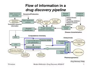
Pipeline flow. Pipeline flow- current preprocessing order (not necessarily the ideal one!). 4. Try to measure (using calib. lamp) & undo vertical distortions. 2. Try to measure (using calib. lamp) & undo slant. 0. Starting point.

E N D
Pipeline flow- current preprocessing order (not necessarily the ideal one!) 4. Try to measure (using calib. lamp) & undo vertical distortions 2. Try to measure (using calib. lamp) & undo slant 0. Starting point 5. Apply a horizontal spatial freq. filter to subtract fan/comb component 1. Try to measure (using calib. lamp) & undo trace 3. Try to measure & divide out slit illumination profile (using current image itself) 6. Trim the image down and fit a sinusoidal model to the intensity at each wavelength
Pipeline flow- intermediate data product “whirl” and RV extraction Phases: [1.3, 1.4, 6.28, 2.0] Amplitude/DC offset: [0.02, 0.05, 0.00001, 0.034] Normalized fluxes: [0.98, 0.56, 0.9999, 0.71] 7. Record sine fit parameters and fluxes at each wavelength into a multi-extension FITS file (“whirl”) 8. For each star or calibration source to have radial velocity measured, choose template epoch 8a. For each other epoch, do chi-squared minimization to find best fitting velocity (x and y axes treated as separate velocity parameters; final answer used is the y-velocity only) 9. For star exposures only, subtract off barycentric velocity 10. For star exposures only, subtract off apparent lamp velocity derived from adjacent lamp exposures from the final star velocity. 11. Write RV’s to disk as a FITS table.
Glossary of jargon: slant: Where light of a given wavelength does not fall in a vertical line on the raw image. trace: Where the brightest part of the slit image does not fall in a horizontal line on the raw image. illumination profile: The intensity as a function of position on the slit, for one spectrum distortion: The non-uniformity of the size of pixels covering the long axis of the slit image. LSF: The line-spread function- the final 1-D profile on the raw image of a delta function at the slit, along the wavelength direction. PSF: The point-spread function- the final 2-D profile on the raw image of a delta function at the slit, along both the wavelength and slit (spatial) direction. whirl: The 1-D extracted spectrum of fluxes, augmented with phase as a function of wavelength and fringe visibility as a function of wavelength. sine fit: The model used to fit the intensity along the slit direction, at a given wavelength fringe freq./period: The omega or period parameter of the sinusoid used in the sine fit. preprocessing: All processing steps involving fixing the image and doing sine fits. RV extractor: All processing steps starting using the whirl, not requiring access to the image. TIO: A calibration lamp spectrum- a blackbody spectrum shining through an iodine gas absorption cell prior to entering the fibre feed. Stands for Tungsten + IOdine. ThAr: A calibration lamp spectrum- a Thorium-Argon emission lamp shining into the fibre feed. ThArNF: A ThAr spectrum with no fringes: a diffuser plate is slid into the instrument after the interferometer and prior to the slits, thus scrambling out the interferometer fringes. Tung: A calibration lamp spectrum- a blackbody spectrum from a tungsten lamp. Sine source: A calibration lamp spectrum- a spectrum with a sinusoidal intensity as a function of wavelength. long fibres: The fibres from the instrument room to the telescope enclosure. short fibres: The fibres inside the cartridge, attached to the plug plate.