Download
1 / 12
120 likes | 124 Views
(ABSORBER) FOCUS COIL MODULES. FC. SSU. SSD. FOCUS COIL MODULES. Two modules built by Tesla UK Contain two ‘Gradient Coils’ on common aluminium bobbin Absorber is contained in warm bore. Indirect cooling ~ 20 Litre external He channel Two cryocoolers, 3 watts. Two coils operated in:

E N D
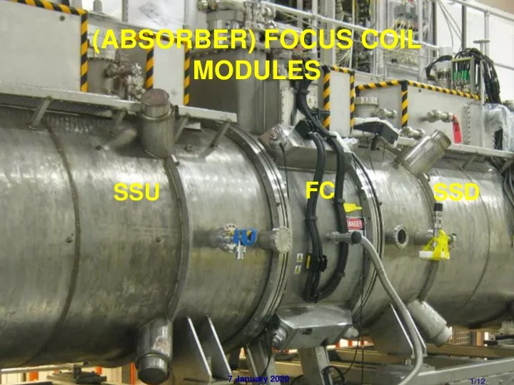
(ABSORBER) FOCUS COIL MODULES FC SSU SSD
FOCUS COIL MODULES • Two modules built by Tesla UK • Contain two ‘Gradient Coils’ on common aluminium bobbin • Absorber is contained in warm bore
Indirect cooling ~ 20 Litre external He channel Two cryocoolers, 3 watts • Two coils operated in: • ‘Solenoid mode’ = same polarity • ‘Flip mode’ = opposite polarity • More demanding: ~ 2 x higher currents ~ 2 x higher fields at conductors ~ 4 x higher internal forces: ~ 300 tons at max. I • Powered in series from one PSU
FC INDUCTANCES & CURRENTS • PRY has very small – ~ 0.5% – effect on L • Proposed currents for Step IV running: • 56 to 86 Amps in Solenoid Mode • 172 Amps in Flip Mode • U = 1.9 MJ
CM SUSPENSION SYSTEM • 8 ‘Futura’ straps • Pre-tensioned to ~ 140 kN • Support up to 90 tons axial force • Unbalanced forces on CM of up to ~ 30 tons in Step IV with asymmetrically powered SSs • Load cell on each strap Load cells 3 months from cooldown
TRAINING • Design currents: • 188 A Flip mode • 120 A Solenoid mode • Expected (hoped) for 20% more • FC 2 reached 225 A after 3 quenches • FC 1 required 21 training runs • Did not reach design current • Stable at 180 A, Flip mode • 2 x 24 hour periods • Currently installed • Solenoid mode OK • Environment with powered SSs will be different After warm up
VOLTAGE TAPS • 8 Voltage taps per coil • QD system compares: • Voltages between adjacent pairs of VTs • Protects HTS and LTS tails, e.g. V2 – V3 and V3 – V4 • Threshold ~ 20 mV • and voltages across coils 1 QD channel
COIL VOLTAGE COMPARISON • Voltages across coils compared • Threshold ~ 0.6 Volts • Duplicated for redundancy • Could be triggered by dI/dt of SSU > ~ 650 mA/sec • due to different induced voltages in coils PSU Balance
QD SYSTEM – SUMMARY • 6 channels • Channels 1,2, 5 and 6 protect HTS and LTS tails • Channels 3 and 4 detect quenches in coils • Amplified outputs available for logging
LOGGING SYSTEMS • SLOW • Uses ‘Picologger’ • Amplified QD outputs (differences) recorded • FAST • ADCs record VT signals directly ~ 60 mSec
AFTER QUENCH • QD system detects quench: • Contactor opens • Current flows through diodes & 2 x 1.5 ohm dump resistors • Voltage tap across dump resistors powers heaters on each coil (not shown) • Forces other coil to quench • Quench all over in 10 – 15 seconds • 80 – 90 % of stored energy dumped inside module Dump resistors & diodes external to module