Download
1 / 12
120 likes | 288 Views
MICE Model and MICERun. MiceModel: Overall Model that is used throughout G4MICE to represent any stage of the experiment in any level of detail. Representations of the model are produced for specific purposes (e.g. Simulation: GEANT4, Reconstruction: RecPack, Visualisation: HepRep, X11, ???)

E N D
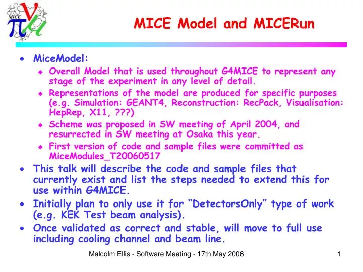
MICE Model and MICERun • MiceModel: • Overall Model that is used throughout G4MICE to represent any stage of the experiment in any level of detail. • Representations of the model are produced for specific purposes (e.g. Simulation: GEANT4, Reconstruction: RecPack, Visualisation: HepRep, X11, ???) • Scheme was proposed in SW meeting of April 2004, and resurrected in SW meeting at Osaka this year. • First version of code and sample files were committed as MiceModules_T20060517 • This talk will describe the code and sample files that currently exist and list the steps needed to extend this for use within G4MICE. • Initially plan to only use it for “DetectorsOnly” type of work (e.g. KEK Test beam analysis). • Once validated as correct and stable, will move to full use including cooling channel and beam line. Malcolm Ellis - Software Meeting - 17th May 2006
Model vs Representation • We need a single “Model” of any given setup in MICE (or any MICE test beam). • For different applications (e.g. Simulation, Reconstruction, Visualisation) application specific “Representations” are derived from this one model. • This allows us to guarantee that (for e.g.) the geometry used in the Reconstruction is the same as that for the Simulation (if we want it to be). • Each representation extracts the information from the model that is needed for that particular task. Malcolm Ellis - Software Meeting - 17th May 2006
MICERun • Added to Interface • Analogous to MICEEvent, however is the place where classes that live for longer than an event will live: • MiceModule (the MICE modeling class) • Calibration classes • Decoding classes • Analysis classes? • etc... Malcolm Ellis - Software Meeting - 17th May 2006
MiceModule • Found in the Config package. • A MiceModule represents a sub-component of MICE at any level and may have a “Mother” module and/or one or more “Daughter” modules. • Each MiceModule has a name, a physical shape (a simple way of describing the rough volume occupied and orientation, etc), a position, an orientation and any number of “Properties” which can be of type bool, int, double or string. • The SciFi tracker can be represented at two extremes by either: • A single MiceModule which represents the solenoid’s position and orientation • Every individual fibre, represented as core plus two layers of cladding, in every plane, in every station, with carbon fibre support arms, etc, etc, etc.. • More likely: something in between these two! Malcolm Ellis - Software Meeting - 17th May 2006
Properties • Properties are for component specific properties that the Modeling code does not need to understand, but which one or more representations will need to know. • Examples: • Simulation: • Radiation length • Composition • Density • Reconstruction: • Station number • Plane number • Visualisation: • Colour • Not all representations will need to know about all properties, and a property can always be added without breaking the existing functionality of any representation (e.g. add colour to an object has no effect on simulation) • Properties will also be used in the same way as existing data cards to define the detailed geometries of complicated objects, e.g. torispherical absorbers. Malcolm Ellis - Software Meeting - 17th May 2006
Files • For a given configuration of detectors and other hardware, there will exist a configuration file that lists the location of each module and its orientation and the name of a file describing that module. • Each module can then have zero or more sub modules described in it, again giving their location with respect to this module. • Each module can return its location and orientation with respect to any other module that it is inside of, up to and including the global coordinate system (i.e. “MICE hall”). • In this manner, alignment is achieved by (for example) placing a given station in a given tracker at a slightly different from nominal position and/or orientation. • This can also be used to make Simulation studies of the effects of misalignments, etc... Malcolm Ellis - Software Meeting - 17th May 2006
MICEFILES • Latest tag expects a new environment variable: • setenv MICEFILES ${MICESRC}/FILES/ • This is used in the MiceModule code in order to know where in the tree to the right it should look for configuration and module information. • A single MiceModule instance is made in the MICERun from a configuration: • MiceModule* module = new MiceModule( "KEKOctober2005/KekOctoberTrackerOnly.dat" ); • It then reads that file and loads all the Modules that have been referred to into a tree of MiceModules hanging below this highest level instance. Malcolm Ellis - Software Meeting - 17th May 2006
Volume Types • Currently only two types supported, can be extended as required: • Cylinder – A Cylinder defined as having its circular faces perpendicular to the z axis with a given radius and length. • Box – A regular box defined as an extent along the X, Y and Z axes. • The volumes are defined by the physical extents. • The module then has a location of the centre of this volume and the orientation allows it to be rotated arbitrarily from the definition above. • These volumes are NOT meant to provide an Engineering drawing level of accuracy! • Rather, they indicate the approximate volume occupied by the module and aid in simple representations. • More complicated representations will make use of module specific properties. Malcolm Ellis - Software Meeting - 17th May 2006
Sample Configuration • A first (incorrect and incomplete!) version of a configuration has been committed to represent the KEK test beam configuration. • An application “MiceModules” has been added to enable testing and development of this code. • The main configuration file looks like: // FILES/Models/Configurations/KEKOctober2005/KekOctoberTrackerOnly.dat // // A model of the KEK test beam setup in which only the 4 station tracker // prototype is described // // M.Ellis 16th May 2006 ConfigurationKekOctoberTrackerOnly { ModuleTracker/KekFourStationTracker.dat { Position 0.0 0.0 0.0 mm Rotation 0.0 0.0 0.0 degrees } } Malcolm Ellis - Software Meeting - 17th May 2006
Module Definitions // FILES/Models/Modules/Tracker/KekFourStationTracker.dat // // Definition of the tracker module for the four station prototype // tested in the KEK pi2 beam line in October 2006 // // M.Ellis 16th May 2006 ModuleKekFourStationTracker { Volume Cylinder Dimensions 50.0 150.0 cm PropertyDouble MagneticField 0.0 PropertyDouble RedColour 1.0 PropertyDouble GreenColour 1.0 PropertyDouble BlueColour 1.0 ModuleTracker/KekStationB.dat { Position 0.0 0.0 475.0 mm Rotation 0.0 0.0 0.0 degrees } ModuleTracker/KekStationA.dat { Position 0.0 0.0 -73.0 mm Rotation 0.0 0.0 0.0 degrees } ModuleTracker/KekStationC.dat { Position 0.0 0.0 -325.0 mm Rotation 0.0 0.0 0.0 degrees } ModuleTracker/KekStationD.dat { Position 0.0 0.0 -475.0 mm Rotation 0.0 0.0 0.0 degrees } } // FILES/Models/Modules/Tracker/KekStationD.dat // // Definition of Station D as used in the four station tracker prorotype // in the KEK test beam of October 2006 // // M.Ellis 16th May 2006 ModuleKekStationD { Volume Cylinder Dimensions 30.0 0.5 cm PropertyInt Station 2 Module Tracker/KekViewX.dat { Position 0.0 0.0 -0.5 cm Rotation 0.0 0.0 0.0 degrees } ModuleTracker/KekViewV.dat { Position 0.0 0.0 0.0 cm Rotation 0.0 0.0 120.0 degrees } Module Tracker/KekViewW.dat { Position 0.0 0.0 0.5 cm Rotation 0.0 0.0 -120.0 degrees } } Malcolm Ellis - Software Meeting - 17th May 2006
Tree of Modules Configuration KekOctoberTrackerOnly Has 1 daughter: Module KekFourStationTracker is at position (0,0,0) Volume is a Cylinder with Radius 500 and Length 1500 Double property BlueColour has the value 1 Double property GreenColour has the value 1 Double property MagneticField has the value 0 Double property RedColour has the value 1 Has 4 daughters: Module KekStationB is at position (0,0,475) Volume is a Cylinder with Radius 300 and Length 5 Integer property Station has the value 2 Has 3 daughters: Module KekViewX is at position (0,0,-5) Volume is a Cylinder with Radius 300 and Length 1.5 Integer property View has the value 2 Double property BlueColour has the value 1 Double property Pitch has the value 0.422 Has 1 daughter: Module CentralFibre is at position (0,0,0) Volume is a Cylinder with Radius 0.175 and Length 300 Module KekViewV is at position (0,0,0) Volume is a Cylinder with Radius 300 and Length 1.5 Integer property View has the value 1 Double property Pitch has the value 0.422 Double property RedColour has the value 1 Has 1 daughter: Module CentralFibre is at position (0,0,0) Volume is a Cylinder with Radius 0.175 and Length 300 Module KekViewW is at position (0,0,5) Volume is a Cylinder with Radius 300 and Length 1.5 Integer property View has the value 3 Double property GreenColour has the value 1 Double property Pitch has the value 0.422 Has 1 daughter: Module CentralFibre is at position (0,0,0) Volume is a Cylinder with Radius 0.175 and Length 300 • MiceModule class has a simple printTree method which dumps the information that has been instantiated in a given module and all its daughters. • Example from the KEK configuration (a fraction of the full output): Malcolm Ellis - Software Meeting - 17th May 2006
Next Steps • Need someone (Lara?) to test and fix where necessary the MiceModule code. • Extend visualisation representation of MiceModule (see Visualisation talk) for use in checking models. • Tracker group (Aron, Atsushi, Hideyuki, Makoto and Malcolm) work on complete and correct description of the KEK tracker test setup (tracker, solenoid, TOF, defining counters, etc) • Migration to use of MiceModule as already described in the Reconstruction plan talk. Malcolm Ellis - Software Meeting - 17th May 2006