Download

1 / 36
370 likes | 475 Views
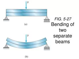
Chapter 5 Analysis and Design of beams for Bending. Beams for Bending. This part is devoted to the analysis and design of beams. Beams are structural members supporting loads applied at various points along the member. They are usually straight long and prismatic.

E N D
Chapter 5 Analysis and Design of beams for Bending
Beams for Bending This part is devoted to the analysis and design of beams. Beams are structural members supporting loads applied at various points along the member. They are usually straight long and prismatic The beam supporting the overhead cranes system shown are subjected to transverse loads causing the beams to bend. We will determine the normal stresses in beams resulting from transverse loads. Transverse loading causes only bending and shear in the beam. When the loads are not at a right angle to the beam, they also produce axial forces in the beam
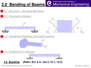
Introduction Objective:Analysis and design of beams Beams are structural members supporting loads at various points along the member Transverse loadings of beams are classified as concentrated loads or distributed loads Applied loads result in internal forces consisting of a shear force (from the shear stress distribution) and a bending couple (from the normal stress distribution)
Classification of Beam Supports Statically determinate beams: the reactions of the support of a beam involve only three unknowns that can be determined by the method of statics Statically indeterminate beams: the reactions of the support of a beam involve unknowns that cannot be determined by the method of statics alone. Deformations of the beam should be used to solve for the unknowns.
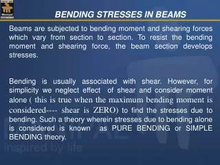
Introduction If we pass a section through a point C of a beam, the internal forces in the section will consist of a shear force V and a bending moment M. The bending moment M creates normal stresses in the cross section, while the shear force creates shearing stresses. In most cases the dominant criterion in the design of a beam for strength is the maximum value of the normal stress in the beam. In this part we will determine the normal stresses due to the bending moment M. The determination of the shearing stresses resulting from the shear force is left for the next chapter.
Introduction Normal stress due to bending σm is inversely proportional to S thus selecting a beam with a large section modulus is important. σm is proportional to the magnitude of M thus it is important to determine the magnitude and location of the maximum bending moment.
Shear and Bending Moment Diagrams Determination of the maximum normal and shearing stresses requires identification of maximum internal shear force and bending moment. The shear force and bending moment at a point are determined by passing a section through the beam and applying an equilibrium analysis on the beam portions on either side of the section. Sign conventions for shear forces V and V’ and bending couples M and M’
Example 1 5-10: Draw the shear and bending moment diagrams for the beam and loading shown, and determine the maximum absolute value (a) of the shear, (b) of the bending moment.
Example 2 5-23: Draw the shear and bending-moment diagrams for the beam and loading shown, and determine the maximum normal stress due to bending.
Example 3 5-24: Draw the shear and bending-moment diagrams for the beam and loading shown and determine the maximum normal stress due to bending.
Example 4 5-29: Knowing that P = Q =480 N, determine (a) the distance a for which the absolute value of the bending moment in the beam is as small as possible, (b) the corresponding maximum normal stress due to bending.
Load, Shear, and Bending Moment When a beam carries more than two or three concentrated loads, or distributed loads, the method outlined before will become quite cumbersome. Relationship between load and shear: VD-VC = - (area under load curve between C and D)
Load, Shear, and Bending Moment Relationship between load and bending moment: MD-MC = (area under shear curve between C and D)
Example 5 5-45: Draw the shear and bending-moment diagrams for the beam and loading shown, and determine the maximum absolute value (a) of the shear, (b) of the bending moment.
Example 6 5-57: Draw the shear and bending-moment diagrams for the beam and loading shown and determine the maximum normal stress due to bending.
Design of Prismatic Beams for Bending The design procedure: Determine the value of σall for the material selected from a table of properties of the material Draw the shear and bending diagrams corresponding to the specified loading conditions and determine |M|max Determine the minimum allowable value Smin Among the beam section choices which have an acceptable section modulus, select the one with the smallest weight per unit length smallest cross sectional area (least expensive)
Example 7 5-67: For the beam and loading shown, design the cross section of the beam, knowing that the grade of timber used has an allowable normal stress of 12 MPa.
Example 8 5-77: Knowing that the allowable normal stress for the steel used is 160 MPa, select the most economical S-shape beam to support the loading shown.
Example 9 5-90: Beams AB, BC, and CD have the cross section shown and are pin-connected at B and C. Knowing that the allowable normal stress is +110 MPa in tension and -150 MPa in compression, determine (a) the largest permissible value of P if beam BC is not to be overstressed, (b) the corresponding maximum distance a for which the cantilever beams AB and CD are not overstressed.