Download
1 / 72
780 likes | 892 Views
Industrial applications of ionizing radiation sources (Destructive Single Event Effects) Andrea Candelori Istituto Nazionale di Fisica Nucleare and Dipartimento di Fisica, Padova. Material for study.

E N D
Industrial applications of ionizing radiation sources (Destructive Single Event Effects) Andrea Candelori Istituto Nazionale di Fisica Nucleare and Dipartimento di Fisica, Padova
Material for study 1) F. W. Sexton, “Destructive Single-Event Effects in Semiconductor Devices and ICs",IEEE Trans. Nucl. Sci., vol 50, n.3, June 2003, pp. 603-621, and references therein.
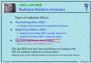
Single event effects (SEE) Definition: “Single event effects (SEE) are individual events which occur whena single incident ionising particle deposits in a sensitive volume of the device enough energy in form of ionization to cause an effect in a device”. Single event effects (SEE) can be: -destructive events: Single Event Burnout (SEB) in power MOSFET Single Event Gate Rupture (SEGR) power MOSFET Single Event Snapback (SES) in MOSFET Single Event Latch-up (SEL) in CMOS technologies -non destructive events: Single Event Upset (SEU) Single Event Drain Current Collapse (SEDC2) Single Event Transient (SET) Single Event Disturb (SED) Single Event Functional Interrupt (SEFI)
Ionization track: reminder 0.1 m An energetic ionizing particle going through a semiconductor material creates a track of ionization with a radius typically less than 1 m (i.e., higher than the minimum channel length of the current CMOS technologies) and within which the carrier density decreases from the center.
Ion shunt effect Illustration of the ion shunt effect: the high charge density along a track can connect devices junctions.
Charge funneling: reminder Microscopic mechanism If an ion track traverses a reversed biased p-n junction the density of ionization can be so high that the resulting current flow collapses the field across the junction and the collection charge from the track reaches father into the semiconductor than the original depletion region. Definition Charge funneling is the extension of the charge collection from an ionization track to a region beyond the original depletion depth: The charge funneling effect.
Single Event Effects (SEE) cross section: reminder The cross section () for Single Event Effects is: =NSEE/ NSEE: Number of SEE observed : Particle fluence WEIBUL FIT = sat{1-exp[-(L-Lth)/W]S} sat: saturation value of the cross section Lth: threshold value for LET W and s are fitting parameter A typical measured and ideal SEE cross section curve.
C P+ E B N E P B C N P N+ Bipolar Junction Transistor (BJT): reminder PNP type NPN type IE= IB+IC Condition base-emitter junction base-collector junction Cut-offreverse biasedreverse biased Active region (BE inverse)reverse biasedforward biased Active region (BE direct)forward biasedreverse biased Saturationforward biasedforward biased Equations in active region Equations in saturation IC= IBbIC,max= IB, max b IC is the collector current, IB is the base current, b>>1 is the gain.
Power MOSFET -Power MOSFETs are power devices capable of conducting large currents when turned in the ON state and withstanding large voltage when turned in the OFF state. -Current flow between the n-drain (substrate) and the n+-source in power n-MOSFET is turned ON and turned OFF for positive values of the drain-to-source voltage VDS by modulating the surface conductivity under the poly gate which is controlled by the gate-to-source voltage (VGS) -The n+-source and the p-body contacts are short-circuited. Cross section of a typical n-channel power MOSFET Current flow in a n-channel power MOSFET
Power n-MOSFET operation -VGS<0 V: the n-epi surface region at the SiO2/Si interface becomes depleted and then approach to strong inversion. The channel region (p-body surface region along the Si/SiO2 interface) approach strong accumulation. The power n-MOSFETis turnedOFF and no current flows. -VGS>0 V: the n-epi surface region at the SiO2/Si interface approaches strong accumulation. The channel region (p-body surface region along the Si/SiO2 interface) becomes depleted and approach strong inversion, forming a n-type channel along the SiO2/Si surface that couples the drain (substrate) with the source. Thepower n-MOSFET turned ONand current flows. -The threshold voltage (VTH) is the minimum gate source voltage (VGS) to turn on the n-type channel at the SiO2/Si interface. Current flow in a n-channel power MOSFET Cross section of a n-channel power MOSFET
Power MOSFET Advantages: -fast switching time; -high current capability; -low on resistance; -low gate current. Applications: -on-board space system; -battery charge assemblies; -power supply electronics; -power conditioning systems; -momentum wheels and controllers.
Power MOSFET Power MOSFETs: large current capabilities are achieved by the parallel connection of thousands of smaller units cells. Cross section of a n-channel power MOSFET Cross-section for parallel connectionsof n-channel power MOSFETs.
IE NPN type N+ N+ VBE E p VCE IB B N P N C IC Power n-MOSFET: parasitic BJT 0 V 0 V 0 V I 0 V I V>0 V>0 0 V 0 V I V>0 The parasitic npn Bipolar Junction Transistor (BJT) inherent to a power n-MOSFET.
Power n-MOSFET: Single Event Burnout (SEB) and the parasitic BJT 0 V I 0 V >0
IE NPN type N+ N+ VBE E p VCE IB B N P N C IC Power n-MOSFET: Single Event Burnout (SEB) and the parasitic BJT -A single high-energy heavy ion is capable of destroying a power n-MOSFET. -the ion going through the voltage supporting layer of the device generates high density of electron-hole pairs along its track, which can induce highcurrent density up to 104 A/cm2in presence of large drain-to-source voltages. -for VDS>0 (VBS=0 and VGS≤0 can be varied) the hole current density flowing from the n-epi substrate (collector) through the p-body region (base) below the lateral channel region may cause a voltage drop exceeding 0.7 V for the base-emitter p-n junction, turning on the parasitic bipolar junction transistor (emitter=n-source, base=p-body, collector=n-epi layer) that is an inherent part of the power MOSFET, locally increasing the plasma current several order of magnitude. -the resulting very localized power density may be large enough to produce incandescent temperatures, which are able to lead the device burn-out. 0 V 0 V I I I >0
Power n-MOSFET: Single Event Burnout (SEB) and the parasitic BJT The electric field intensity in the lightly doped n-epi region was the main contribution to SEB sensitivity in power n-MOSFET (VDS>0, VBS=0 and varying VGS0): -a heavy ion strike close to the n-source (emitter) region generate a dense plasma of electrons and holes along the track of the ion strike. -electrons flow to the n-drain (collector) region while holes are swept to the p-body (base) diffusion. -As excess holes move through the p-body spreading resistance to the ground contact, a voltage drop develops that forward biases the parasitic base (p-body)-emitter (n-source) junction. -Forward biasing leads to further electron injection into the lightly doped n-epi region, which, under high field condition,then generates additional holes through avalanche multiplication. Current in the n-epi layer increases regeneratively until the device enters second breakdown and thermal runway. 0 V D 0 V I e h >0
Power n-MOSFET: Single Event Burnout (SEB) and the parasitic BJT Right side Electrons flow to the n-drain (collector) region Holes are swept to the p-body (base) diffusion As excess holes move through the p-body spreading resistance to the ground contact, a voltage drop develops that forward biases the parasitic base (p-body)-emitter (n-source) junction. Forward biasing leads to further electron injection into the lightly doped n-epi region, which, under high field condition,then generates additional holes through avalanche multiplication. Current in the n-epi layer increases regeneratively until the device enters second breakdown and thermal runway.
Power n-MOSFET: Single Event Burnout (SEB) and the parasitic BJT 0 V D V>0 0 V I e E e h >0
Power MOSFET: Single Event Burnout (SEB) Photograph of a power MOSFET after SEB.
Power MOSFET: Single Event Burnout (SEB) [opzionale] Experimental set-up for SEB cross section measurements Non destructive Destructive SEB cross section measurements are independent on IDS and VGS for a fixed VDS and VBS=0 SEB cross section measurements are independent on the load resistance
Power MOSFET: Single Event Burnout (SEB) [opzionale] What can be deduced by this plot? . . . . . . . . . . . . . . . . . . . . . . . . . . . . . . . . . . . . . . . . . . . . . . . . . . . . . . . . . . . . . . . . . . . . . . . . . . . . . . . . . . . . . . . . . . . . . . . . . . . . . . . . . . . . . . . . . . . . . . . . . . . . . . . . . . . . . . . . . . . . . . . . . . . . . . . . . . . . . . . . . . . . . . . . . . . . . . SEB cross section data for the n-power MOSFET "2N6766"(drain-source breakdown voltage BVDSS=200 V) at VDS=200V and VGS=VBS=0V during irradiation
Power MOSFET: Single Event Burnout (SEB) [opzionale] Cu, E=200 MeV LET=28 MeV·cm2/mg Range 40 m I, E=90 MeV LET=30-40 MeV·cm2/mg Range 15 m What can be deduced by this plot? . . . . . . . . . . . . . . . . . . . . . . . . . . . . . . . . . . . . . . . . . . . . . . . . . . . . . . . . . . . . . . . . . . . . . . . . . . . . . . . . . . . . . . . . . . . . . . . . . . . . . . . . . . . . . . . . . . . . . . . . . . . . . . . . . . . . . . . . . . . . . . . . . . . . . . . . . . . . . . . . . . . . . . . . . . . . . . Cl, E=90 MeV LET=16 MeV·cm2/mg Range 25 m SEB cross section data for the n-power MOSFET "2N6766"(drain-source breakdown voltage BVDSS=200 V) at increasing VDS and VGS=VBS=0V during irradiation
Power MOSFET: Single Event Burnout (SEB) [opzionale] Cu, E=200 MeV LET=28 MeV·cm2/mg Range 40 m I, E=90 MeV LET=30-40 MeV·cm2/mg Range 15 m Cl, E=90 MeV LET=16 MeV·cm2/mg Range 25 m What can be deduced by this plot? . . . . . . . . . . . . . . . . . . . . . . . . . . . . . . . . . . . . . . . . . . . . . . . . . . . . . . . . . . . . . . . . . . . . . . . . . . . . . . . . . . . . . . . . . . . . . . . . . . . . . . . . . . . . . . . . . . . . . . . . . . . . . . . . . . . . . . . . . . . . . . . . . . . . . . . . . . . . . . . . . . . . . . . . . . . . . . SEB cross section data for the n-power MOSFET “IRF 130"(drain-source breakdown voltage BVDSS=100 V) at increasing VDS and VGS=VBS=0V during irradiation
Power n-MOSFET: Single Event Burnout (SEB) and the parasitic BJT Factors increasing SEB: -gain of the parasitic npn transistor; -spreading resistance in the base region; -avalanche multiplication in the drain region; -increase of the epitaxial layer thickness and decrease of the doping level (in presence of high electron-hole densities, the peak of the electric field can easily shift from the base-collector junction to the epi-substrate transition region); Power MOSFET can be hardened to SEB by reducing the distance from the p+ plug to the body region.
Power MOSFET: Single Event Burnout (SEB) and the epi-layer Increase of the epitaxial layer thickness and decrease of the doping level (in presence of high electron-hole densities, the peak of the electric field can easily shift from the base-collector junction to the epi-substrate transition region) increase the SEB sensitivity. -Power n-channel MOSFET failed at VDS equal to 20-90% of the rated breakdown voltage of the device (current induced avalanche in the epitaxial region). -Power p-channel MOSFET did not experience SEB up to their rated breakdown voltage. Current Induced Avalanche (CIA), due to electrons, in the epitaxial layer. Power n-MOSFET (left) and test structure (right) for studies on the Current Induced Avalanche (CIA), due to electrons, in the epitaxial layer.
(f) Power n-MOSFET: Single Event Burnout (SEB) and the epi-layer Electric field in the npn structure as a function of the current density -In presence of high electron-hole densities, the peak of the electric field can easily shift from the base-collector junction to the epi-substrate transition region. Then by increasing the electron-hole densities, the value of the electric field increases. -This effects in enhanced by increasing of the epitaxial layer thickness and by decreasing the doping levelincrease, taking into account that an ion generates an high electron-hole density along its tracks, whose densities can be higher than the doping levels. -High electric fields can induce Current Induced Avalanche (CIA), due to electron and holes in the epitaxial layer,increasing the electron-hole densities and the electric field.
Power MOSFET: Single Event Burnout (SEB) SEB depends on the charge distribution along the ion track and not just on the surface LET of the ion: the charge generation at least as deep as the epi-substrate junction contributes to SEB: -higher energy ions (higher range) have a lower threshold to SEB than low energy ion (lower range) with similar LET; -there is lower charge recombination at higher ion energies, due to the larger track diameter. Br 150 MeV Depth Br 285 MeV
Power MOSFET: Single Event Burnout (SEB) For VDS values at 50% of the rate breakdown voltage, with VGS=0V and VBS=0V SEB occurs primarily for ion impacts in the channel region close to the p-base region Ion impact point
Power MOSFET: Single Event Burnout (SEB) Drain current after ion impact Charge collected at the drain node after the ion impact: 1) first peak charge collection at the drain depletion region; 2) increasing LET or VDS a second peak appears: transistor action in the base-emitter junction of the vertical parasitic BJT. Both peaks moves gradually to higher charges by increasing LET or VDS; 3) when SEB occurs a high charge peak appears corresponding to the runway avalanche current condition. The threshold charge QTH depends on technology not on the operating conditions.
Power MOSFET: Single Event Burnout (SEB) -Studies of SEB in power MOSFET by using techniques for preventing SEB, by limiting the current with a series resistor and removing the power within 1 s of detection of high current condition. Experimental set-up
Power MOSFET: Single Event Burnout (SEB) -The SEB sensitivity decreases by increasing temperature because the impact ionization rate decreases by increasing temperature. -Difference between static and dynamic operation: the saturation cross section in dynamic mode can be 2 orders of magnitude lower than in static mode. -By tilting the sample, the 1/cos dependence for LET can not be applied-By increasing the incidence angle the SEB sensitivity decreases. -SEB can be induced also by protons and neutrons.
Power MOSFET: Single Event Gate Rupture (SEGR) -Following an heavy ion strike in the center of the channel region of a power n-MOSFET, the dense plasma of electrons and holes along the ion track separate under the influence of the drain bias (VDS>0 and VGS=VBS=0V). -Electrons are rapidly sweep to the n+ substrate (drain), while hole transport towards the oxide end of the plasma surface and then radially, thought the surface accumulation layer, to the p-body contact where they are collected. -These holes, pooling up against the Si/SiO2 interface, induce an image charge on the gate electrode, leading to a transient increase of the electric field in the gate dielectric. Electric field at the SiO2/Si interface as a function of the radial distance from the heavy ion strike and time following the strike. - + - + - + - + - + - + - + - + - + - + - + - + -
Power MOSFET: Single Event Gate Rupture (SEGR) -A single high-energy heavy ion that does not cause SEB may produce Single Event Gate Rupture (SEGR) which is also capable of destroying the Power MOSFET. -After the ion strike at the center of the gate region holes are driven toward the oxide-end of the filament, at the interface between the n-epitaxial layer and the gate oxide, where they induce an image charge in the gate electrode increasing the oxide field. SEGR occurs when the ion strike far from the p-body region allows a considerable “pool” of holes to be collected at the Si/SiO2 interface before diffusing to ground by the resistive path, locally increasing the oxide electric field beyond the breakdown value. Left: power MOSFET showing an ion strike at the center of the gate region, with holes moving upward and electrons downwards under the influence of the positive drain voltage. Right: The distributed RC-circuit model for the hole storage at the end of the strike filament (CIS capacitors) and the leakage path to the grounded body region (resistors).
Power MOSFET: Single Event Gate Rupture (SEGR) Power n-MOSFET test: fixed VDS,VGS=-1V, =4·104 ions/cm2 Maximum operating conditions specified by the manufacturer Breakdown limit for VDS: 0 V <VDS< 73V Oxide breakdown limit for VGS: -39V <VGS<0 V
Power MOSFET: Single Event Gate Rupture (SEGR) Power n-MOSFET test: fixed VDS,VGS=-1V, =4·104 ions/cm2 Increasing LET Effect of the ion on the oxide. Response of the substrate
Power MOSFET: Single Event Gate Rupture (SEGR) Power n-MOSFET (tox=50 e 150 nm, VDS=0 e 15 V) Effect of the ion on the oxide. Increasing LET Response of the substrate This expression is independent on the channel (n or p) type
Power MOSFET: Single Event Gate Rupture (SEGR) 1998: measure of the current increase for SEGR detection and quick ion beam irradiation stop, for accurate reading of the fluence to SEGR: first measurements of the SEGR cross-section.
Power MOSFET: SEB and SEGR Power n-MOSFET Region I: low VDS values SEGR. Region II: intermediate VDS values SEGR and SEB. Region III: high VDS values SEB. SEB can be prevented by limiting the drain current SEGR can not be prevented
Power MOSFET: SEB and SEGR -SEGR sensitivity increase for ion impact in the center of the channel -SEB sensitivity decreases for ion impact in the center of the channel and on the p+ body region.In source regions SEB occurs only at high LET values. Maximum SEGR Maximum SEB To decrease SEGR sensitivity, decrease the channel length To decrease SEB sensitivity, extend the p+ plug under the source
MOSFET: Single Event Snapback (SES) NPN type E C N+ N P B Heavy ion induces snapback in MOSFET: (a) ion injection into the depletion region; (b) movement of electrons and holes; (c) activation of the parasitic Bipolar Junction Transistor (BJT) inherent to a MOSFET.
VIN VOUT High Low Low High VDD S p-channel MOSFET B VIN VIN D VOUT D VOUT n-channel MOSFET B S VSS CMOS inverter The inverter is the simplest CMOS logic gate. -When a low voltage (0 V) is applied at the input, the top p-type MOSFET is conducting(switch closed) while the bottom n-type MOSFET behaves like an open circuit: the supply voltage (5 V) appears at the output. -When a high voltage (5 V) is applied at the input, the bottom n-type MOSFET is conducting (switch closed) while the top p-type MOSFET behaves like an open circuit: the output voltage is low (0 V). -The function of this gate can be summarized by the following table: CMOS inverter schematic (left) and standard symbol (right).
VIN P-MOSFET N-MOSFET D D B S S B S D D S VDD VSS B B p-channel MOSFET n-channel MOSFET VOUT CMOS inverter: Single Event Latch-up -A single high-energy heavy ion is capable of destroying a CMOS inverter by turning on the inherent p-n-p-n structure: Single Event Latch-up (SEL) CMOS inverter:schematic (left) and physical cross section view (right) showing the inherent p-n-p-n structure triggering the Single Event Latch-up (SEL).
C P+ E B P-MOSFET N-MOSFET N E P B C D D B S S B N P N+ CMOS inverter: the inherent p-n-p-n structure NPN type IE= IB+IC PMOS NMOS PNP type B n+ D S p+ D S n+ B p+ C E p NPN PNP n CMOS inverter:physical cross section view showing the inherent p-n-p-n structure triggering the Single Event Latch-up (up) and equivalent circuits of the p-n-p-n structure (down) implementing two parasitic BJT transistors.
VDD VSS VDD P-MOSFET N-MOSFET B n+ S p+ S n+ B p+ N+ P+ N+ P+ P+ E B RS RS N P N C RW RW C E C P E E N+ N+ B B P+ P P P-Well C P B N N PNP NPN N-Substrate VSS CMOS inverter: the inherent p-n-p-n structure Right BJT Left BJT Base and collector are in common Physical cross section (left) and equivalent circuits (right) of the p-n-p-n structure with the two parasitic BJT transistors..
VDD VDD P+ E B RS RS N P N C RW RW C P E N+ N+ B P+ P P N N VSS CMOS inverter: the inherent p-n-p-n structure VSS N-MOSFET P-MOSFET B n+ S p+ B p+ S n+ N+ P+ P+ N+ E C E B P-Well C P B PNP NPN N-Substrate Right BJT Left BJT Base and collector are in common Physical cross section (left) and equivalent circuits (right) of the p-n-p-n structure with the two parasitic BJT transistors..
CMOS technology: Single Event Latchup (SEL) -In normal operating condition the two parasitic BJT are in high impedance state because the base and the emitter are shortened. -The collector of first BJT is connected to the base of the second BJT and viceversa: an unstable loop is thus inherent to the CMOS technology (IC=IBb). -Under external excitation (electrical or radiation) one parasitic BJT may be forced into conduction activating the unstable loop condition. -A self-maintained low-impedance path is opened between the supply terminal VDD and VSS that may be followed by a permanent thermal failure. -This destructive effect for the CMOS technology is called Single Event Latchup (SEL) Physical cross section (left) and equivalent circuits (right) of the p-n-p-n structure.
CMOS inverter: I-V characteristics of the p-n-p-n structure -Once the break-over voltage is surpassed the devices leave the forward blocking region and passes through the negative resistance region to the ON region. -If the operating point is such that the device current is higher than the holding current IH and the device voltage is greater than the holding voltage VH, latchup is maintained. -In order to eliminate the latchup condition, it is necessary to disconnect the power supply. -Any condition that place the operating point to the ON region can trigger the latchup: an ion strike can turn on one or either the two parasitic BJTs and the resulting operation point may results in the latchup condition. Equivalent circuit (left) and I-V characteristic of the p-n-p-n structure.
SEL: n-well CMOS technology: p-MOSFET in n-well and n-MOSFET in p substratewith parasitic pnpn structure Test structure for Single Event Latchup studies Equivalent circuit for the pnpn structure
Single Event Latchup Example of SEL cross section curve induced by ions: 1) the 1/cos() law can be used for SEL; 2) the cross section in saturation is approximatively equal to the well area, i.e. SEL is related to the activation of the vertical parasitic BJT in the pnpn structure.
Single Event Latchup -Latchup can be induced directly by ions and indirectly by protons and neutrons. -Latchup induced indirectly by protons and neutrons appear with the technology scaling down. -Latch-up sensitivity increases with temperature as a consequence of the bipolar gain increase with temperature. What can be deduced from the figure? By increasing the temperature the SEL threshold . . . . . . . . . and the SEL saturation value . . . . . . . . . .