Download
1 / 42
411 likes | 428 Views
The automatic extinguisher control panel is designed in accordance with European standards EN54-2 and EN54-4 Fire Detection and Fire Alarm systems - Control and Indicating Equipment and EN12094-1 Fixed firefighting systems - Components for gas extinguishing systems. Shop it at https://www.vedardsecurity.com/fire-fighting-gas-extinguish-alarm-panel-4-zone-p-61

E N D
JB-QB-QTC5015 Gas Fire-extinguishing Control Panel Installation and Operation Manual Ver. 1.0 May 2015 JB-QB-QTC5015 Gas Fire-extinguishing Control Panel Installation and Operation Manual China·Liaoning·Yingkou Tiancheng Fire Protection Equipment Co., Ltd Chapter One Introduction of JB-QB-QTC5015 Gas Fire-extinguishing Control Panel
JB-QB-QTC5015 Gas Fire-extinguishing Control Panel Installation and Operation Manual Ver. 1.0 May 2015 Chapter Two Structure and Configuration Instruction 2.1Typical Control Panel Configuration and Inner-Structure Instruction 2.2Control Panel Board Instruction 2.3Inner-Structure and Connection Instruction 2.3.1Control Panel Structure Instruction 2.3.2Control Panel Connection Terminals Instruction 2.3.3Cabling Requirements Chapter Three Installation and Commission 3.1Container Opening Test 3.2Installation Condition and Methods of Control Panel 3.3Boot Test 3.4Peripheral Device Test 3.5Connection and Setup 3.6Commission Chapter Four Common User Manual 4.1Boot/Shutdown and Self-Test 4.2Preparation for Keypad Operation 4.3Operation Level 4.4Device Registration and Registration Test 4.5Information Display and Record 4.6Mute 4.7FireAlarm and Fault Resolution 4.8Disable and Enable of Device 4.9Loop Control Panel Controlled Device's Manual Start/Stop 4.10Loop Control Panel Controlled Device's Auto Linkage Control 4.11Reset Function 4.12Emergency Start/Abort of Gas Fire-extinguishing 4.13Start and Stop of Sounder strobe Chapter Five SystemAdministrator Manual 5.1User Setup 5.1.2Device Disable 5.1.5Print Setup 5.2.1Device Registration 5.2.2Working Mode 5.2.3Loop Component Setup 5.2.4Direct Control Panel Setup 5.2.5LCD Repeater Panel Setup 5.2.6Simulation FireAlarm 5.2.7Password Setup 5.2.8Gas Fire-extinguishing Output Setup 5.2.9Factory Default Setup 5.3Network Setup 5.3.1Networking Mode 5.3.2LocalAddress
JB-QB-QTC5015 Gas Fire-extinguishing Control Panel Installation and Operation Manual Ver. 1.0 May 2015 5.4Linkage Program 5.4.1Common Linkage Program 5.4.2Offline Program 5.5Linkage Mode Setup 5.6Gas Spray Control Setup Chapter Six Direct Control Panel Configuration 6.1Direct Control Introduction 6.2Direct Control Characteristics 6.3Direct Control Technical Specifications 6.4Direct Control Structure Features 6.4.1Panel Board Instruction 6.4.2Direct Control Panel Instruction Chapter Seven Fault, Abnormal Information Operation and Regular Test 7.1Troublieshooting 7.2Regular Test and Replacement Chapter Eight Note
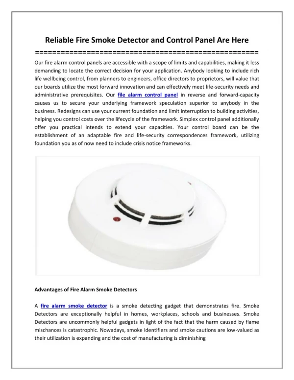
JB-QB-QTC5015 Gas Fire-extinguishing Control Panel Installation and Operation Manual Ver. 1.0 May 2015 Preface JB-QB-QTC5015 Intelligent Fire Alarm Control Penal /Gas Fire-extinguishing Control Panel is an intelligent all-in-one control Unit combined of fire alarm linkage and gas fire-extinguishing control with our company’s market demand research and years of construction experience. As a wall-mounted and modularized style, JB-QB-QTC5015 has the features of strong functions, reliability and configured flexibility. LCD display adopts Chinese character in a large colored screen. The printer can print all system alarms, faults, operations in Chinese and has the capacity of overall field program. Devices can be connected to JB-QB-QTC5015 control Panel include smoke sensor, heat sensor, flame detector, manual alarm button, emergency start/abort button, sounder strobe, LCD repeater panel, gas spray indicator, auto/manual switch module and output module. This control panel has the ability of fire detection and gas fire-extinguishing, control of four fire protection zones and one fire alarm loop. JB-QB-QTC5015 can also be used as an interconnection panel connecting to JB-TG-TC5000 fire alarm control panel (linkage), JB-LT-TC5200 fire alarm control panel (linkage) or JB-TB-TC5120 fire alarm control panel (linkage) to form a networking mode. JB-QB-QTC5015 control panel is an indoor equipment which meets relevant gas fire-extinguishing control panel requirements from GB4717-2005<fire alarm control panel> and GB16806-2006<fire protection linkage control panel>. For detailed tech parameters and manuals of detector and module, please refer to relevant installation instruction. This brochure must be taken charge of and kept by specialized staff for further usages.
JB-QB-QTC5015 Gas Fire-extinguishing Control Panel Installation and Operation Manual Ver. 1.0 May 2015 Part One General Introduction Introduction of JB-QB-QTC5015 Intelligent FireAlarm Control Panel/ Gas Fire-extinguishing Control Panel JB-QB-QTC5015 Intelligent Fire Alarm Control Penal/Gas Fire-extinguishing Control Panel (short as Control Panel) is a new all-in-one generation of control panel combined of fire alarm linkage and gas fire-extinguishing control. The control panel also has linkage control function for construction designation need and the function to be compatible with other products to form up a fire alarm linkage integral control system, which is suitable for fire alarm and fire protection linkage integral control system. The control panel has the function of gas fire-extinguishing and can be applied for four zones. The control panel can be connected to emergency start/abort button, sounder strobe, gas spray indicator, auto/manual switch module and input/output module. With the function of networking, the control panel can also be connected to TC5000 series fire alarm control panel to form up a fire alarm and gas fire-extinguishing control system. 1.1Strong functions and High Reliability Intelligent loop control is adopted so maximum 255 bus system alarm linkage points (addressable detector, module, LCD repeater, etc.) for one alarm loop. Isolation designation is applied for loops in order for high anti-interference, reliable system and convenience of field operation and commission. 1.2Colored Chinese Character Menu Display Interface The overall Chinese character menu display is clear and vivid for convenient usage. Simple operation can realize system multifunction. 1.3Flexible Modularized Structure and Multifunction Configuration Options The control panel is consisted of various functional modules whose structure is pull and plug style, suitable for configuration, installation, system commission and maintenance and later expansion. 1.4Intelligent Configured Direct Control Point The control panel can be configured with six loops of three-circuit/three-bus direct control panel point and detect output short circuit or open circuit. These tests enable connection reliability between control module and important devices. 1.5Configurable Chinese Character LCD Repeater Panel The control panel can be connected to Chinese character LCD repeater panel through bus system loop. Installation is convenient and reliable. Alarm device type and Chinese note can be displayed on the panel. 1.6Connection with Field Devices through Loop Control Emergency start/abort button, gas spray indicator, sounder strobe and auto/manual switch can be connected to the panel easily. Thus cabling, construction, commission and latter maintenance are simplified and construction cost can be reduced. 1.7Networking Function The control panel is connected to fire alarm control panel through CAN bus system to form up a fire alarm network. Remote display of its status can be realized. Chapter One Part Two Structure Installation Commission
JB-QB-QTC5015 Gas Fire-extinguishing Control Panel Installation and Operation Manual Ver. 1.0 May 2015 Chapter Two Structure and Configuration Instruction 2.1Typical Control Panel Configuration and Inner Structure Instruction JB-QB-QTC5015 control panel shall be installed wall-mounted, of which the typical configurations include: loop control part, loop part, direct control part, gas fire-extinguishing control part, power, etc. The system is a combination of alarm, linkage and gas fire-extinguishing. Control of fire alarm, common fire protection device start/abort and gas fire-extinguishing device can be realized through loop control panel or direct control panel. Appearance sketch of JB-QB-QTC5015 is shown as Fig. 2-1: Fig. 2-1 Includes: (1) mainframe (2) direct control part (six loops) (3) gas fire-extinguishing control part 2.2Control Panel Board Instruction Fire alarm control panel board is consisted of display operation zone, Direct control zone and gas fire-extinguishing control zone and shown as below: 1)Display operation zone Display operation zone is shown as Fig. 2-2
JB-QB-QTC5015 Gas Fire-extinguishing Control Panel Installation and Operation Manual Ver. 1.0 May 2015 Fig. 2-2 Display operation board is consisted of LCD, indicators, keypad and printer. Indicators are instructed as below: ●Fire alarm indicator: red, illuminates when control panel detects peripheral detector at alarm status, specific information is shown on the LCD screen. After alarm eliminated, press 'reset' to black out the indicator. ●Fault indicator: yellow, illuminates when control panel detects fault from peripheral device (addresses 201-255 of loop one and detector, module or LCD repeater panel of loop two) or panel itself, specific information is shown on the LCD. After alarm eliminated, the indicator blacks out. ●Start indicator: red, illuminates when control panel gives out start order to peripheral device, specific information is shown on the LCD. Press 'reset' to black out the indicator. ●Supervisory Indicator: red, illuminates when control panel gives out supervisory signal to peripheral device, specific information is on the LCD. Press 'reset' to black out the indicator. ●Feedback Indicator: red, illuminates when control panel receives feedback signal from peripheral device, specific information is on the LCD. Black out when no feedback signal. ●Main power Indicator: green, illuminates when control panel is powered byAC220V. ●Standby indicator: green, illuminates when control panel is powered by standby power. ●Standby fault indicator: yellow, illuminates when fault occurs to battery system. Black out after battery system fault eliminates. ●Disable indicator: yellow, peripheral device needs to be disabled when fault happened. After repair or replacement, peripheral device can be restored with enable function. Illuminates when disable device exists. ●Sounder strobe start indicator: red, illuminates when 24V output through sounder strobe junction or 2 loop addressed sounder strobe activated. Black out neither 24V output through sounder strobe junction nor 2 loop non-addressed sounder strobe activated. ●Sounder strobe fault indicator: yellow, illuminates when sounder strobe output junction disconnected or short circuit or 2 loop addressed sounder strobe fault happened. Black out when fault restored. ●Sounder strobe disable indicator: yellow, illuminates when sounder strobe output junction disabled or 2 loop addressed sounder strobe disabled. ●Commission indicator: yellow, illuminates when system under commission. Spray module shall not be activated under this condition. ●Mute indicator: green, illuminates when 'mute' pressed and speaker stops alarm after control panel gives out alarm sound. Black out when new alarm occurs and alarm sounds again. ●System fault indicator: yellow, illuminates when system malfunctions.
JB-QB-QTC5015 Gas Fire-extinguishing Control Panel Installation and Operation Manual Ver. 1.0 May 2015 Operational keypad functions are listed as below: 2)Direct Control Zone: Direct control zone sketch is listed as Fig. 2-3 Fig. 2-3 Direct control zone sketch is listed as Fig. 2-3 Direct control zone is consisted of six manual start areas, each with one button, three indicators and one label. Start indicator illuminates red if corresponding unit button is pressed and control order is given out. If corresponding device responses, feedback indicator illuminates red. Fault indicator illuminates yellow when peripheral junction open circuit or short-cut. Customer can write down corresponding device on the button and fix on corresponding label of manual panel. Direct control buttons are operational enabled under the condition of 'direct control buttons enabled'. 3)Gas Fire-extinguishing Control Part Fig. 2-4 Indicator Instruction for Each Zone: ✧ ✧Running Indicator: green, illuminates when running normally in this zone. ✧ ✧Auto Status Indicator: green, blacks out when this zone is in manual status, illuminates in auto status. ✧ ✧Fault Indicator: yellow, illuminates when fault on loop control device or connection fault with electromagnetic valve or pressure valve in this zone. Black out when fault eliminated or reset by control panel. ✧ ✧Sounder Strobe Start Indicator: red, illuminates when field sounder strobe activated in this zone.
JB-QB-QTC5015 Gas Fire-extinguishing Control Panel Installation and Operation Manual Ver. 1.0 May 2015 ✧ ✧Start Control Indicator: red, illuminates when start order given out by pressing 'spray start', field emergency start button or control panel. Black out when start order cancelled. ✧ ✧Delay Indicator: red, illuminates for this zone gas fire-extinguishing delayed period, black out after this period. ✧ ✧Spray Start Indicator: red, illuminates when spray start signal given out in this zone, black out after reset. ✧ ✧Spray Indicator: red, illuminates after pressure button being pressed in this zone (volt-free closed signal), black out after reset. Buttons Instruction: 'Spray Start’ Button for Each Zone: Start delayed gas fire-extinguishing period in this zone for the first press. Press again during the delayed period and confirm, this zone will stop the delayed period and start gas fire-extinguishing immediately. 'Delay Stop’ Button for Each Zone: during the delayed period in this zone, this button pressed will stop the delayed period, the sounder strobe and started output module. 'Sounder strobe start/stop’Button in Each Zone: Start and stop control of sounder strobe in this zone. Start for the first press and stop for the second press. Control buttons of each gas fire-extinguishing zone are operating enabled under 'gas button' enabled condition. 2.3Inner Structure and Connection Instruction 2.3.1Control Panel Structure Instruction Control panel case, the core part of control panel, is consisted of mainboard, loop mainboard and loop (communication) board. Fig. 2-4 2.3.2Control Panel Peripheral Terminals Instruction Includes: L, N, PE: AC 220V terminals andAC grounding terminals, L+, L-: non-polarized alarm loop signal bus system terminals, Qn+, Qn-: non-polarized gas loop signal bus system interface, n: gas zone, No. 1~4, NO, CM, NC: fire alarm volt-free output interface (NO: volt-free open junction, CM: volt-free sharing junction, NC: volt-free closed junction), SG+, SG-: sounder strobe control output terminals (volt control point, active output DC24V, output DC24V stopped after manually stopped or reset), A2, B2: RS485 terminals connecting figure display in fire protection control room, A2 for A point of 485, B2 for B point of 485, A1, B1: RS485 terminals,A1 forA point of 485, B1 for B point of 485 (optional),
JB-QB-QTC5015 Gas Fire-extinguishing Control Panel Installation and Operation Manual Ver. 1.0 May 2015 Qn, Gn, Hn: direct control interface of three-wire system, n for loop No. for three-wire system, No. 1~6, CH, CL: polarized Can bus system of control panel networking; JP2: pin set at the peripheral networking terminal on loop mainboard. Short cut piece jumps to ON when the panel is connected to peripheral network terminal, 24V, GND: linkage power output terminals. 2.3.1Cabling Requirements 1) L+, L- shall adopt section area≥1.0mm2twisted pair, single connecting wire resistance no larger than 20Ω, otherwise enlarge the section diameter. 2) Qn+, Qn- shall adopt section area≥1.0mm2twisted pair, single connecting wire resistance no larger than 20Ω, otherwise enlarge the section diameter. 3) Power wire 24V, GND shall adopt section area≥1.0mm2RV wire. 4) NO, CM, NC, SG+, SG, Qn, Gn, Hn shall section area≥1.0mm2RV wire. 5)A1, B1 shall adopt section area≥1.0mm2twisted pair, no longer than 1000m. 6)A2, B2 shall adopt section area≥1.0mm2twisted pair, no longer than 500m, 7) Steel cylinder output (i.e. spray start module output, for output capacity see input/output module parameter) drive connect wire for each zone shall adopt section area≥2.5mm2twisted pair or section area≥4.0mm2twisted pair if cable longer than 50m so as to guarantee electromagnetic valves minimum working voltage. 8) Spray feedback signal interface (i.e. spray start module answer point) connect wire for each zone shall adopt section area≥1.0mm2RV wire. 9) CH, CL networking CAN bus system shall adopt section area≥1.0mm2twisted pair, no longer than 1000m. 10)AC power wire shall adopt triplex cable with voltage resistance≥750V. 11) Enclosure grounding wire shall adopt 4.0mm2copper conductor, grounding resistance no larger than 4Ω. Chapter Three Installation and Commission 3.1Container Opening Test Test the field devices before installation 3.1.1Construction Configuration Test Test whether the control panel equipment packing list is in accordance with the construction configuration. After opening the package, check with the list the contained commodities include: installation instruction, control panel keys, etc. After check verified, check the appearance necessarily. If any inconformity occurred, please contact our after-sale department. 3.1.2Control Panel Inner Configuration and Connection Check Check whether inner-connection between each components is correct. Please contact our after-sale department if any disconnection, inconformity with the instruction occurred. 3.2Case Installation Condition and Pattern Panel Dimension (L*W*H): 385mm*134mm*510mm Environment Temperature: 0℃~+40℃ Relative Humidity: ≤95%, no condensing Wall mounted installation shall be adopted. 3.3Boot Test The control panel shall be connected to power and turned on for check once placed in the field.
JB-QB-QTC5015 Gas Fire-extinguishing Control Panel Installation and Operation Manual Ver. 1.0 May 2015 Tests include: ✧LCD, digital pipe and indicator operate well. ✧Run self-test to check if the indicators and digital pipes can illuminate and the speaker can give out three consecutive loud sounds. ✧In normal supervision status, observe if any power or keypad button malfunctions. If printer included, check if printer functions well. Please contact our after-sale department, if any malfunction occurred. 3.4Peripheral Devices Test 3.4.1Peripheral Wire Connection Condition Test Check the bus system connection with the control panel, measure bus system insulation resistance to ground and loop loading status. The insulation resistance between bus system and ground shall be larger than 20 MΩ (using insulation meter). 3.4.2Device Test Check if loop device installation is in compliance with design requirements. Eliminate existing fault and prepare for system connection. 3.5Cabling and Setup If every test meets the requirements after test of mainframe and peripheral devices, please set the connection between peripheral devices and mainframe, direct control points and gas zone referring to relevant instruction from Chapter Two. 3.6Commission 3.6.1System cabling, circuit testing and insulation resistance. Turn off the panel to measure if insulation of this loop is about 5 KΩ (loop fully loaded). Measure if the insulation resistance between loop and ground is beyond 20M with a megger. (Parallel two circuit before measuring, otherwise devices on bus system may be damaged.) 3.6.2Install base, module and LCD repeater panel and connect to wire. 3.6.3Encode corresponding detectors and modules of gas fire-extinguishing, address distributed as below: Name Gas Loop Coding Range (Loop 1) Zone 1 Zone 2 1 51 2~10 52~60 11~20 61~70 21~30 71~80 31~40 81~90 Zone 3 101 102~110 111~120 121~130 131~140 Zone 4 151 152~160 161~170 171~180 181~190 Input/output Module (spray start output) InputModule (spray feedback) Input/output ( gas spray indicator control) Sounder Strobe Emergency Start/Abort Button orAuto/manual Relay Input/output Module (linkage related devices) 41~50 91~100 141~150 191~200 Warning: cut off the connection between each zone and electromagnetic valve or switch panel mode to commission mode due to gas extinguisher’s special performance, in case of irrevocable losses of wrong spray caused by improper operation or circuit problem. 3.6.4Fire alarm control panel bus system has 2 loops with 255 addresses and can be connected with TC5000 series bus system equipment. 3.6.5Register loop component and test registration result by operating the panel to be correct. If mass loss happened, test power and bus system then devices respectively, and register again. After
JB-QB-QTC5015 Gas Fire-extinguishing Control Panel Installation and Operation Manual Ver. 1.0 May 2015 registration, check if corresponding addresses are complete. 3.6.6Field program, linkage logic program and Chinese character note input can be realized through control panel USB flash drive with a computer. 3.6.7Run detector alarming test and check if note content is in compliance with field situation. 3.6.8Auto linkage experiment. If auto linkage malfunction. Check module function. If circuit and module function well, check whether logic relation is correct and peripheral linkage device malfunction. 3.6.9Operator needs to be trained for the right operation methods. Control panel can be put into action after test verified.
JB-QB-QTC5015 Gas Fire-extinguishing Control Panel Installation and Operation Manual Ver. 1.0 May 2015 Part Three SystemApplication Chapter Four Common User Manual Instruction 4.1Boot/Shutdown and Self-test After commission completed, user can turn on the panel and operate following steps: ●Turn on the power of related devices. ●Turn on general and standby power of control panel. Above steps completed, the system will be powered and initialized (shown as Fig. 4-1). Initialization completed, the system enters normal supervisory status. A 'self-test' button, placed on the mainframe keyboard, can be pressed to enter sounder strobe test. Shutdown process needs to switch off in reverse of turning on. Be cautious that standby power must be turned off, otherwise may cause damages to the battery. Fig. 4-1 4.2Keypad Operation Preparation 4.2.1Order Function and Character Function of Keypad Most keys on the control panel are dual-function buttons, of which the lower is order function and the upper is character function. Order function works only under supervisory status and mostly restricted by lock key. Character function works after entering menu to put in data. 4.2.2Common Input of Data When inputting data, an area on the screen will be highlighted to indicate location and range of inputting data. Highlight and previous character will vanish after data inputted. Input continues from this character. One character being edited, the following will be highlighted and the highlight will return back to the starting one after all edited. Inputted data will be stored after 'enter' pressed, no matter where the cursor is; no data will be stored and customer exists from current editing page after 'cancel' pressed. 4.2.3Common Method of Information Query
JB-QB-QTC5015 Gas Fire-extinguishing Control Panel Installation and Operation Manual Ver. 1.0 May 2015 ' query' button pressed will help system show the alarm information query page and press No. key for corresponding information. Press right arrow key to shift between fire alarm page and linkage page in alarm linkage information page. Press '▲'、'▼' to display information for choice. Press 'cancel' to return to upper page or system operation interface. 4.3Operation Level Operation level includes 'Level I', 'Level II' and 'Level III'. The starting level after turning on is 'Level I' when 'mute', 'query' and 'setup query' can be functioned and 'Operation Level: Level I' is displayed at the lower status bar of the LCD. 'User Setup, self-test, reset, start, stop, disable, enable, linkage mode and sounder strobe start/stop' can be functioned at Level I. 'System setup, network setup and linkage setup' can be functioned at Level III. Choose 'operation level', press No. key for operation level and LCD displays a password page. Input correct user password and press 'enter' to enter corresponding level for authorization. Exist after no action in 30s to level I. 4.4Device Registration and Registration Test 4.4.1Device Registration Press 'menu' for main menu, press 5 for '5. system setup', choose '1. device registration' and press 'enter' to start system registration. The system will reset automatically after registration completed. 4.4.2Registration Test 'Test' pressed, the LCD will display total registration sum, fault sum and disable sum of control panels in the system. 4.4.3Loop Configuration Test Press 'menu' for main menu, press 1 for '1. system information' shown as Fig. 4-2. This page displays device species and sum in the system. Fig. 4-2 Press 1 under the condition of Fig. 4-2 to enter loop board information page (Fig. 4-3).
JB-QB-QTC5015 Gas Fire-extinguishing Control Panel Installation and Operation Manual Ver. 1.0 May 2015 Registered device sum, loop current and reference voltage of each loop displayed on this page can reflect working condition of this loop. Press No. key to enter corresponding loop information page on this page shown as Fig. 4-4. Fig. 4-4 Press 'F1' for device information query as shown in Fig.4-4 to enter loop device information page. Information is shown as Fig. 4-5.
JB-QB-QTC5015 Gas Fire-extinguishing Control Panel Installation and Operation Manual Ver. 1.0 May 2015 Fig.4-5 Loop device information page displays: device code, registered type, 2nd code, device attribute and note in Chinese character (see device definition chapter one for specifics). upper or lower query. Registered type refers to loop panel controlled device type and device attribute refers to defining of input module includes type for fire alarm, feedbacks and supervisory. Press 'F2' to enter loop status browse page for browsing loop status as in Fig. 4-4. Loop controlled device answer current is displayed on this page. Loop status can be reflected according to this Fig. 4.5Information Display and Record 4.5.1Information Display Information will be displayed if any of fire alarm, linkage, supervision, fault or shield occurred. If more than one piece of information occurs, the system will display information in the order of gas/control information or fire alarm/linkage than supervisory than fault than disable. Press 'query' to shift between information pages. Press 'query' for query menu and press 1 for fire alarm query. Shown as Fig. 4-6. Press '▲'、 '▼' for Fig. 4-6 Fig. 4-6 shows fire alarm and linkage information. Press '▶' to shift between fire alarm page and linkage information page. If gas delayed information occurs, it will be shown at the bottom two lines. Press 'query' for query and press' 6' for gas query page shown as Fig. 4-7.
JB-QB-QTC5015 Gas Fire-extinguishing Control Panel Installation and Operation Manual Ver. 1.0 May 2015 Fig. 4-7 Fig. 4-7 is gas and control information page. Press ' ▶ ' to shift between gas and control information page. 4.5.2History Record Query Press 'menu' for main menu and press '3' for history information query, shown as Fig. 4-8. Fig. 4-8 At page in Fig. 4-8, press '1' for alarm record to enter alarm history information page shown as Fig. 4-9. Fig. 4-9 Alarm history record displayed in the system includes occurring time, loop, address, type,2nd code and Chinese character note. 4.6 Mute Speaker gives out warning sound and indicates when fire or fault happens. Press to light 'mute' indicator and stop speaker. Indicator blacks out when new alarm occurs and warning sound given out again. When gas feedback occurs and control panel gives out gas feedback sound (pulsing peeps), mute cannot function. 4.7FireAlarm and Troubleshooting
JB-QB-QTC5015 Gas Fire-extinguishing Control Panel Installation and Operation Manual Ver. 1.0 May 2015 4.7.1Common Troubleshooting Faults can be divided into two: general control system fault e.g. power/battery fault, loop control panel fault, etc.; field device fault e.g. detector fault, module fault, etc. ' Mute' can be pressed to stop fault alarm when fault occurs. Standby power needs to be applied when main power was down, but cannot supply for more than eight hours. Otherwise the power switch (standby power switch included) must be cut off in case of damage. The system must be cut off, taken record and sent for maintenance when fault occurs. When fault occurs on field devices, they must be maintained on time. If the fault cannot be eliminated on time, use the isolator to isolate the device from loop and release the isolated device after fault eliminated. 4.7.2Common Resolution of FireAlarm When fire alarm occurs, check the alarm spot if fire actually occurs. If confirmed as false alarm, notify and resolute it. If confirmed as fire, organize fire extinguishing immediately. 4.8Device Disable and Enable When fault occurs to peripheral device (detectors, modules or repeaters), disable the fault device and enable the device once maintained or replaced. 4.8.1Device Disable Press 'disable' (password is needed when control panel is under locked condition) and the screen will display as Fig. 4-10. Fig. 4-10 Assume address 1 on loop 1, Addressable Photoelectric Smoke Detector as the disabling device. Isolation operations are as listed: ✧Input address and loop of isolating device, ✧Press F1 for isolation status of the device, if not isolated, it will be added to isolation list. 4.8.2Enable Press 'enable' (password is needed when control panel is under locked condition) and the screen will display as Fig. 4-11.
JB-QB-QTC5015 Gas Fire-extinguishing Control Panel Installation and Operation Manual Ver. 1.0 May 2015 Fig. 4-11 Assume address 1 on loop 1, Addressable Photoelectric Smoke Detector as the enabling device. Enable operations are as listed: ✧Input address and loop of enabling device, ✧Press F2 for enable status of the device, if disabled, it will be deleted from disable list. 4.9Manual Start/Stop Operations of Loop Controlled Devices 4.9.1Conditions for Manual Operation of Peripheral Devices Peripheral devices are for fire protection usage ONLY. Wrong operation may cause unnecessary loss or weakening of previous fire protection. Operating staff must be cautious about the operation! Start of peripheral devices shall adopt following rules: ✧ ✧Operating staff must be trained and qualified, ✧ ✧Operating staff must be fully aware of device starting environment and controlling zones; ✧ ✧Operating staff must be fully aware of device starting function and accept subsequent consequence. Manual start and stop of loop control panel controlled device needs inputting address and loop. The manual start order can be given out only under the status of 'manual'.
JB-QB-QTC5015 Gas Fire-extinguishing Control Panel Installation and Operation Manual Ver. 1.0 May 2015 Fig. 4-12 Fig.4-13 4.10Auto Linkage Control of Loop Controlled Devices 4.10.1Auto Linkage Satisfaction Auto linkage order can be given out when control panel under 'all-auto' or 'part-auto' conditions. Manual start of loop panel controlled devices is preferred when on-duty staff exists. 4.10.2Auto Linkage Logics Satisfaction Control panel gives out start order to start corresponding device when logic relation in linkage formula is satisfied. Resort to 5.4 Design ofAuto Linkage Formula for detailed programming. 4.11Reset Function Press 'reset' and input password to operate erase to control panel after alarm or fault eliminated. Reset can realize listed functions: ✧Erase current alarm, fault and action display, ✧Reset all loop control panel controlled devices and all condition indicators of manual alarm start panel, ✧Erase requiring and delay requiring orders,
JB-QB-QTC5015 Gas Fire-extinguishing Control Panel Installation and Operation Manual Ver. 1.0 May 2015 ✧Erase all mute conditions. ✧Erase isolation display, but isolation action or isolation indicator excluded. Disable information will be displayed again after entering isolation or release isolation operation. 4.12Emergency Start/Abort of Gas Fire-extinguishing After alarm confirmed and all staff are evacuated from gas spray zone, emergency manual start can be enacted through the following ways: ●Field emergency start/abort switch: press emergency start/abort switch in field alarm zone, ●Start operation on board: Set 'gas button enable' for manual operation, Press 'spray start' for corresponding zone on the board and LCD will display delay for this zone as Fig. 4-14. Fig.4-14 Gas spray confirmation during alarm zone start delayed period: Set manual status to 'gas button enable', Press 'spray start' of corresponding zone on the board until 'press enter to start now' lit on the LCD, Press 'enter' on the board. After entering start delayed period, control panel gives out start signal to start delayed zone, lit 'start control', 'delay' and 'sounder strobe start' indicators on the board and alarming sound. Delayed information shown on the LCD, zone sounder strobe gives out field acoustic-optic alarm and output module activates peripheral fire-fighting device. When start delayed period ended or spray starts immediately, 'delay' on the panel board blacks out and 'spray start' illuminates. Control panel gives out DC24V signal to start electromagnetic valve and spray start information shown on the LCD. Feedback signal received from pressure switch, control panel starts field gas spray indicator for gas spray information. Emergency abort can be realized with field emergency stop button or 'emergency abort' on the Start operation of network fire alarm control panel: Set alarm zone as 'auto', Networking fire alarm control panel gives out gas spray start order to alarm zone.
JB-QB-QTC5015 Gas Fire-extinguishing Control Panel Installation and Operation Manual Ver. 1.0 May 2015 board during delayed period. Delay stop and delay indicator blacks out, sounder strobe and output module stop and system returns to previous status before delayed period. Note: Emergency abort button is valid only in the delayed period before ‘spray start’, not before delayed period nor after ‘spray start’. 4.13Start and Stop of Sounder Strobe Control panel can manually start and stop registered field sounder strobe in each zone to give out field acoustic-optic alarm. When manual status is at 'manual enable', gas fire-extinguishing control can: Manually start field sounder strobe with ‘sounder strobe’ on the board when it is at the status of stop. Manually stop field sounder strobe with ‘sounder strobe’ on the board when it is at the status of start. Sounder strobe at 'start': when alarm occurs, control panel starts sounder strobe output and all addressed sounder strobe in loop 2. Sounder strobe at 'stop': when alarm occurs, control panel starts peripherally addressed sounder strobe in loop 2 and 201~255 points of loop 1. Chapter Five SystemAdministrator Manual 5.1User Setup Press 'menu' then '4' to enter 'user setup' menu shown as Fig. 5-1. Fig. 5-1 5.1.1 Date&Time Press '1' after entering 'user setup' and input password for 'date&time' menu shown as Fig. 5-2. After alternation, press enter to store new time.
JB-QB-QTC5015 Gas Fire-extinguishing Control Panel Installation and Operation Manual Ver. 1.0 May 2015 Fig. 5-2 5.1.2Device Disable Press '2' after entering 'user setup and input password for 'device disable' shown as Fig. 5-3. Fig.5-3 5.1.3Alarm Setup Press '3' after entering 'user setup' and input password for 'alarm setup shown as Fig. 5-4.
JB-QB-QTC5015 Gas Fire-extinguishing Control Panel Installation and Operation Manual Ver. 1.0 May 2015 Fig. 5-4 Fault test and start output both set as ON: when alarm occurs, DC24V output from sounder strobe output terminal. Fault test sets as OFF and sounder strobe output disabled, with disable indicator ON: when alarm occurs, no DC24V output from sounder strobe output terminal. Fault test sets as ON, start output sets as OFF with sounder strobe disabled indicator OFF: when alarm occurs, no DC24V output from sounder strobe output terminal. 5.1.4Transmit Setup Press '4' after entering 'user setup' and input password for 'transmit setup' shown as Fig.5-5. Fig.5-5 When fault test and device reg. set as ON, information from control panel can be transmitted to device, when fault test sets as OFF, device transmitting disabled with indicator ON. When fault test sets as ON, device reg. sets as OFF with indicator OFF and transmitting device fault occurs, control panel cannot display disabled device. 5.1.5Print Setup Press '5' after entering 'user setup' and input password for 'print setup' and LCD will display print setup menu shown as Fig. 5-6.
JB-QB-QTC5015 Gas Fire-extinguishing Control Panel Installation and Operation Manual Ver. 1.0 May 2015 Fig.5-6 No information can be printed under 'printer OFF' condition. New occurred information can be printed under 'printer ON' condition. 5.2System Setup Press menu then '5' to enter 'system setup shown as Fig. 5-7. Fig.5-7 5.2.1Device Registration Press '1' after entering 'system menu' and input password for 'device reg.' shown as Fig. 5-8. Fig.5-8 5.2.2Working Mode Press '2' after entering 'system 'setup' and input password for 'working mode' to select working mode, commission mode or normal mode for the control panel. 5.2.3Loop Component Setup Press '3' after entering 'system setup' and input password for 'loop component setup' shown as Fig. 5-8.
JB-QB-QTC5015 Gas Fire-extinguishing Control Panel Installation and Operation Manual Ver. 1.0 May 2015 Fig.5-8 Content and Procedures of Field Device Definition Peripheral devices in field connected with the control panel include fire detectors, linkage module, LCD repeater panel, etc. which need to be encoded both original address and field address. Device definition, item three of system setup menu, means field coding of an original encoding device either a registered or not registered one. 'Original address' is consisted of device's loop No. and its address No. Loop No. is consecutively setting of one and two. Press 'enter' after coding complete. ' 2nd code of user' is a code consisted of eight No. from zero to nine. This is a manual defined No. for specified field address for the device which is easy for user to identify device address and relevant information. Specifications for 2nd code of user: First and second No. represent device building No. ranging zero to ninety-nine. Building No. means an independent building, e.g. a garden community consisted of some buildings, each building can be called an independent building. Third No. represents unit No. in the building, ranging zero to nine. If a building is consisted of three units, each is called a unit. Fourth and fifth No. represents stories No. For the convenience of defining underground floor, first ground floor is defined ninety-nine, second ground floor is defined ninety-eight and by such analogue. No. six, seven and eight represent relevant room No. of loop controlled device and other recognized code. 'Device type' needs to input three numbers referring to device type from device type sheet. 'Device attribute' can be used for setting up peripheral device as 'alarm', 'feedback' and 'supervisory' represented by 0, 1 and 2 respectively mainly for defining input module attribute. 'Note' represents device address and other information in Chinese, max ten Chinese characters. Note: 1) in device definition, onlyArabic numbers can be inputted, other else considered illegal. 2) Full Chinese Pinyin Romanization is adopted for Chinese character input. Press '▶' for next letter after one. Press 'F1' after input and Chinese character will be numbered below, input corresponding No. and Chinese character will be input into the note. 5.2.4Direct Control Panel Setup
JB-QB-QTC5015 Gas Fire-extinguishing Control Panel Installation and Operation Manual Ver. 1.0 May 2015 Press '4' after entering 'system setup' and input password for 'direct control panel setup' shown as Fig. 5-9. Fig. 5-9 Input direct control panel key No. and relevant setup information then press relevant 'enter' for setup. Press 'cancel' after complete to exist setup. 'Key No.' is in correspondent with start operation No. on direct control panel. ' 2nd code of user' is a code consisted of eight No. from zero to nine. This is a manual defined No. for specified field address for the device which is easy for user to identify device address and relevant information. Specifications for 2nd code of user: 'Device type' needs to input three numbers referring to device type from device type sheet. 'Mode' includes 'pulse' and 'consecutive', represented by 0 and 1. 'Detect circuit' includes 'detect (yes)' and 'not detect (No)', represented by 0 and 1. 'Note' represents device address and other information in Chinese, max ten Chinese characters. 5.2.5LCD Repeater Setup Press '5' after entering 'system setup' and input password for 'LCD repeater setup' shown as Fig. 5-10. Fig.5-10 LCD repeater loop circuit controlled needs to be connected before setting display range.
JB-QB-QTC5015 Gas Fire-extinguishing Control Panel Installation and Operation Manual Ver. 1.0 May 2015 Download setting information into LCD repeater and input user code. (transmit a series of devices to LCD repeater with wildcard e.g. 01203*** means transmitting information from all alarm device on third floor in unit two of building one, information includes: loop No., Add. No., user code, device type and Chinese character note.) 5.2.6SimulationAlarm Press '6' after entering 'system setup' and input password for 'simulation alarm' shown as Fig. 5-11. Fig.5-11 Input device loop No. and address, press F1 for indicator ON and F2 for indicator OFF to confirm device address. 5.2.7Password Setup Press '7' after entering 'system setup' and input password for 'password setup'. For system security, password permission is divided as level two and level three. Higher level password can take place of lower one. Relevant password is needed for operation shifting. Password expires after existing from menu of operation, it is needed again when going through these operations. 5.2.8Gas Fire-extinguishing Output Setup Press '8' after entering 'system setup' and input password for 'gas fire-extinguishing setup' shown as Fig. 5-12.
JB-QB-QTC5015 Gas Fire-extinguishing Control Panel Installation and Operation Manual Ver. 1.0 May 2015 Fig. 5-12 Press 0 or 1 to choose pulse or consecutive way. Pulse time is 0~99 sec, output delay is 0~30 sec. After setup, press enter to complete. Factory default is consecutive, 10 sec pulse and 30 sec output delay. 5.2.9Factory Default Setup Press '9' after entering 'system setup' and input password for 'factory default setup' shown as Fig. 5-13. Fig. 5-13 The option will erase all field program data including linkage program, user coding setup, etc. Information cannot be restored after erased, erase will effect after enter pressed. (Be cautious with the operation!) 5.3Network Setup Press '6' after entering 'menu' for 'network setup' shown as Fig. 5-14. Fig.5-14 5.3.1Networking Mode Press '1' after entering 'network setup' and input password for 'networking mode' shown as Fig. 5-15.
JB-QB-QTC5015 Gas Fire-extinguishing Control Panel Installation and Operation Manual Ver. 1.0 May 2015 Fig. 5-15 The control panel is designed as zone panel, set as sub-panel mode. 5.3.2LocalAddress Press '2' after entering 'network setup' and input password for 'local address' shown as Fig. 5-16. Fig.5-16 In networking mode, control panel shall be set a local address ranging 1 to 16 in difference with other panels. 5.4Linkage Program Press '7' after entering 'menu' for 'linkage program' shown as Fig. 5-17.
JB-QB-QTC5015 Gas Fire-extinguishing Control Panel Installation and Operation Manual Ver. 1.0 May 2015 Fig. 5-17 5.4.1Normal Linkage Program Press '1' after entering 'linkage program' and input password for 'normal linkage program' shown as Fig. 5-18. Fig. 5-18 'browse': press '▲' '▼' to scroll linkage program or input No. for required linkage program. Note: space shall be adopted between user 2nd code and device type. Programming ofAuto Linkage Formula Field device refers to devices connected to loop control panel through non-polarized two bus system. The panel offers max 2 loops with 255 points each loop and each device occupies one address. These devices include fire detectors (e.g. rate of rise and fixed temperature heat detector, photoelectric smoke detector, etc.), input modules (e.g. fire hydrant module, flow detector input interface module, etc.), input/output modules (e.g. fire resisting damper, fire hydrant pump control module, etc.), customized burglar alarms, etc. Linkage Formula Format Linkage formula is used to define linkage logic expression between alarm device and controlled device in the system. When status of detecting device or controlling module condition changed, the control panel can operate automatically the start and stop of the device through logic formula.
JB-QB-QTC5015 Gas Fire-extinguishing Control Panel Installation and Operation Manual Ver. 1.0 May 2015 Linkage formula is consisted of two parts between the equal mark, former part is consisted of linkage devices made up of user code and device type, latter part is consisted of user code, device type and relational operator. e.g. Y(01010001 011)=(01010*** 004)_2 means: if any two call points with 2nd code whose former 5 numbers are 01010 sends alarm, No. 01010001 sounder strobe will be activated. Note: 1) '=' means start device if condition met, '=X' means stop device if condition met. 2) Devices at both sides of the linkage formula need to be made up of 2nd code and device type which cannot be omitted and a space between 2nd code and device type. Former part of '=' is 2nd code and device type of linkage device and latter part of '=' is 2nd code and device type of alarm device. Mark of * in each brace of alarm devices represents number of alarm devices that meet the requirements within the brace. 3) Relation mark includes 'and' and 'or'. '+' represents 'or' and 'X' represents 'and'. e.g. Y (01010001 011)=(01010*** 002)_1+(01010*** 004)_1 means: if any smoke detector whose former 5 numbers of 2nd code is 01010 sends alarm OR any call point whose former 5 numbers of 2nd code is 01010 sends alarm, No. 0101001 sounder strobe will be activated. e.g. Y (01010001 001) = (01010*** 002)_1X(01010*** 004)_1 means: if any smoke detector whose former 5 numbers of 2nd code is 01010 sends alarm AND any call point whose former 5 numbers of 2nd code is 01010 sends alarm, No. 0101001 sounder strobe will be activated. 4) Wildcard allowed to use '*' can represent any number from 0 to 9 in a linkage formula, but only for 2nd code in condition part (alarms) not for device type. E.g. 0*001315 represents: 01001315+02001315+03001315+04001315+05001315+06001315+07001315+08001315+090013 15+00001315. 5) There can be only one equal mark representing cause and effect in a linkage formula. 5.4.2Offline Program Press '2' after entering 'linkage program' for 'offline program' shown as Fig. 5-19. Fig. 5-19 5.4.2.1Information Editing Method
JB-QB-QTC5015 Gas Fire-extinguishing Control Panel Installation and Operation Manual Ver. 1.0 May 2015 5.4.2.1.1Software Editing Edit .txt file with Microsoft WordPad or spreadsheet with 'Excel'. 5.4.2.1.2Save Format Format for saving with 'Excel' needs to be called 'text file (tabs divided) (*.txt)'. 2nd code note file needs to be called TCZS.txt or tczs.txt. Linkage program file needs to be called TCLD.txt or tcld.txt. Files can be transmitted only by saved in root directory in USB. 5.4.2.1.3Editing of Device Information (2nd code, note, etc.) Data format: serial number, loop, address, 2nd code, device type, device attribute, sensitivity and note (do not enter this line into file but enter transmission data). e.g. 0001 01 001 03001001010 0 1 note……………… ★'0001' is serial number ranging 0001~9999. ★Press 'tab' not space as separator to add data space. ★'01': loop, 01-96 of which is loop No. of loop controlled device and loop No. of direct controlled device 01-32 ranges from 97-128. ★'001': address, of which No. 0-255 is loop controlled device and No. 0-15 is direct controlled device. ★'03001001': 2nd code (8 numbers). ★'010': device type (3 numbers). Type: 001 heat detector, 002 smoke detector, 003 combined detector, 004 call point, 005 interface, 008 input, 009 output, 010 input/output, 011 sounder strobe, 012 fire hydrant, 005 LCD repeater panel and 016 direct control panel. ★'0': device attribute, '0': fire alarm, '1': feedback, '2': supervisory. Output module can be set as above attributes. ★'1': sensitivity level, this is applied only for smoke detector at three different levels. ★'Note……': note. This can be omitted, max 10 Chinese characters. ★'Enter' is needed as the end of every information input. 5.4.2.1.4Editing of Linkage Program Information Data Format: serial No., disable or enable, linkage program content (do not enter this line into file but enter transmission data). E.g. 0019 0 (03003005 011)=(0300121* 004)_2X(0300122* 004)_2 ★'0019': serial No. 4 numbers ranging 0001-4600. ★Press 'tab' not 'space' as separator to add data space. (F. sat.)
JB-QB-QTC5015 Gas Fire-extinguishing Control Panel Installation and Operation Manual Ver. 1.0 May 2015 ★'0' enable this linkage, '1'disable this linkage. ★Left brace '(' is the start character of linkage expression and right brace ')' is the end. '=' is linkage start, '=X' is linkage stop. Expression between () includes 2nd code (8 numbers), space, device type (3 numbers). Former part of '=' is output part (linkage), and latter part is input part (alarm or feedback). ★'*': wildcard. Arbitrary number among 0-9. When wildcard is applied, '_' and a number 'n' are included in the brace, represents numeral alarms or feedbacks in the brace will meet the requirement. ★Several expressions can be used together linking by '+' for 'or' or 'X', 'x' (capitalized or not) for and. ★'Enter' is needed as the end of every linkage input. ★Total characters for each linkage expression cannot exceed 255 (space included). 5.4.2.2Offline Transmission Method Plug USB to USB-A on the panel's upper left for transmission. For downloading 2nd code note, enter <menu>--<7. Linkage program>--<2. Offline program>--<1. Download 2nd code note> and start downloading 2nd code note. For downloading linkage program, enter <menu>--<7. Linkage program>--<2. Offline program>--<2. Download linkage program> and start downloading. For uploading 2nd code note, enter <menu>--<7. Linkage program>--<2. Offline program>--<3. Upload 2nd code note> and start uploading. Create an empty txt document named READTCZS in the USB before uploading. For uploading linkage program, enter <menu>--<7. program>--<4. Upload linkage program> and start uploading. Create an empty txt document named READTCLD in the USB before uploading. System will automatically reset after download complete. 5.4.2.3USB Format Instruction USB, capacity no larger than 2G can be applied for the system and needs to be formatted as FAT16 before use. 5.5Linkage Mode Setup Press 'linkage mode' button to pop up linkage mode menu shown as Fig. 5-20. Press arrow keys to choose and 'enter' for next item. ' setup complete' will be shown on the screen after setup complete and the system will enter into selected mode. Linkage program>--<2. Offline
JB-QB-QTC5015 Gas Fire-extinguishing Control Panel Installation and Operation Manual Ver. 1.0 May 2015 Fig. 5-20 Note: manual refers to start and stop operation of linkage devices through loop control panel, gas fire-extinguishing control and direct control panel. Manual enable status will be illustrated at the bottom of the screen. Auto refers to automatic linkage operation of the system when linkage conditions are met. Gas fire-extinguishing auto setup refers to permission of system auto zone linkage operation when control panel meets the linkage condition itself or receives gas fire-extinguishing zone linkage order from other panel. 5.6Gas Spray Control Setup Press 'spray control' to pop up spray control menu shown as Fig. 5-21. Press arrow keys to choose and 'enter' for next item. ' setup complete' will be shown on the screen after setup complete and the system will enter into selected mode. Fig. 5-21 When gas spray control setup is enabled, manual or automatic control of gas zone is available, otherwise no operation is allowed. (gas spray control setup is only available for manual control, automatic excluded.Automatic setup is available in gas fire-extinguishing auto setup).
JB-QB-QTC5015 Gas Fire-extinguishing Control Panel Installation and Operation Manual Ver. 1.0 May 2015 Part Four Configuration of Direct Control Panel Devices Chapter Six Configuration of Direct Control Panel 6.1Direct Control Panel Introduction Direct control part is a main component of control panel, designed for important devices include: fire hydrant pump, suction ventilator and forced draft fan in the fire protection and control system. The control panel adopts three wire system. 6.2Direct Control Panel Characteristics JB-QB-QTC5015 fire alarm control panel has six linkage output points controlling six loops of devices, and controls max three loops of emergency start/abort, devices including 1-2, 3-4, 5-6 at customers' needs. Multi-bus output has the function of short circuit, open circuit detecting and corresponding sound instruction and indicators. 6.3Direct Control Panel Technical Specifications 1.Operating Voltage: DC20V~DC28V 2.Output Capacity: max six loops, no loop control address occupied 3.Output Wiring System: three wire system 4.Operating Wiring System: two bus system wires from control panel and two power wires of DC24V 5.Operating Environment: TMP: 0℃~+40℃ Relative humidity≤95%, no condensing 6.4Direct Control Structure Features 6.4.1Board Instruction (1) Fault Indicator: yellow, illuminates when short circuit or open circuit occurs on the panel controlled loop (2) Start Indicator: red, illuminates when control order sent. (3) Feedback Indicator: red, illuminates when controlled device under order responding status. Note: when manual enabled, direct controlled points can be manually controlled directly. 6.4.2Direct Control Panel Instruction 6.4.2.1Part structure of direct control output is shown as Fig. 6-1. Fig. 6-1 Includes: Q, G: start output interface, output DC24V when started. Output current no larger than 200 mA, signal relay loaded and circuit resistance 0.5-2K. H, G: peripheral device answering signal input interface. Answering signal active when
JB-QB-QTC5015 Gas Fire-extinguishing Control Panel Installation and Operation Manual Ver. 1.0 May 2015 volt-free closed, terminal resistance 4.7K. 6.4.2.4Cabling Requirements: RV copper cored conductor section area≥1.0mm2shall be adopted for direct control peripheral point connection wire.
JB-QB-QTC5015 Gas Fire-extinguishing Control Panel Installation and Operation Manual Ver. 1.0 May 2015 Part Five Customer Instruction Chapter Seven Fault, Abnormal Information Resolution and Regular Test 7.1Common Troubleshooting Sheet 1 No Fault Possible Causes 1 No display or abnormal display after turned on cable 2 'power fault' after turned on b.AV fuse blowout Resolutions a. Check 24V power b. Check connecting cable a. Power abnormal b. Disconnection with display a. NoAC power a. Check and connectAC cable b. ReplaceAC fuse (see label for parameters) a. Replace fuse (see label for parameters) b. Open battery box and check connector c. Replace battery after fault not eliminated if powered by AC for more than 8h a. Check and plug 3 'battery fault' after turned on a. Fuse blow out b. Circuit disconnected c. Battery voltage insufficient or damage 4 Loop board comm. fault Peripheral LCD repeater cannot be registered Do not print a. Loop board not plugged 5 Disconnection or bad connection of comm. wire Check power wire and comm. wire of LCD repeater 6 a. Printer nor turned on b. Printer cable bad connected c. Printer failure a. Manual status disable b. Manual fire start panel cable bad connection a. Device connection cut-off b. Device failure Loop control short circuit a. Environment interference b. Relevant part burn-in a. Reset the printer b. Check and connect c. Replace printer a. Reset start mode b. Check and connect 7 Manual button no feedback 8 Device fault a. Check the connection b. Replace device Check the loop a. Check if grounded well b. Contact our tech dep. 9 10 Loop control fault Time fault, storage fault, loop fault, etc. 7.2Regular Test and Replacement Take regular test on devices: print paper belongs to perishable articles, needs to be replaced when insufficient. Take regular test on devices: Cut off connection with electromagnetic valve in each zone before system commission or test in case of irrevocable faculty or losses due to improper operation or start signal output in fault circuit. After disconnection with electromagnetic valve confirmed, switch mode to 'commission',
JB-QB-QTC5015 Gas Fire-extinguishing Control Panel Installation and Operation Manual Ver. 1.0 May 2015 indicator illuminates and system in commission status. Switch to 'normal mode' after commission and indicator blacks out. Note: switch to 'normal mode' after commission or test, otherwise the system will not function.
JB-QB-QTC5015 Gas Fire-extinguishing Control Panel Installation and Operation Manual Ver. 1.0 May 2015 Chapter Eight Notice Turn off the gas fire-extinguishing control panel or switch to 'commission mode' to cut off loop power. Switch to 'normal mode' after test, otherwise the system will not function. Multi meter needs to be applied in any case to test and confirm the electromagnetic safety before connection. DO NOT OPERATE VIOLATELY! To ensure safety, gas fire-extinguishing control panel must be correctly ground wired. Gas fire-extinguishing control panel must be and only can be operated by professional technicians. This panel is precise electronic products and needs to be administrated by specialized staff and keep away from touching. Customers must take on-duty record. If alarm happens, press the 'Mute' and deal with discretion after fire confirmation. Record the operation after action and press 'reset' to erase. If confirmed as miss-alarm and recorded, turn off detector or module and inform our tech service dep. Our company is responsible for maintenance. Please contact our tech service dep. in time if any problems found. Customers are not authorized to apart or maintenance the equipment, otherwise the consequence is at customer's own cost.