Download
1 / 97
1.25k likes | 1.83k Views
Interfacing Techniques CT-4110( 4-3-3). Pre-requisite: Microprocessors. Chapter-1. Introduction to Interfacing Techniques. Definition and Components of interface Classification of Data Transfer Schemes Program controlled transfer Interrupt driven transfer

E N D
Interfacing Techniques CT-4110(4-3-3) Pre-requisite: Microprocessors
Chapter-1 Introduction to Interfacing Techniques
Definition and Components of interface Classification of Data Transfer Schemes Program controlled transfer Interrupt driven transfer Peripheral control transfer (DMA) Outline
Electrical and Mechanical Compatibility Electrical compatibility must be ensured before any thought of connecting two devices occurs. Often the two devices have input and output signals that do not match; if so,the interface serves to match the electrical levels of these signals before the physical connections are made. Mechanical compatibility simply means that the connector plugs must fit together properly. Why interfacing: Contd.
Data Compatibility Just as two people must speak a common language, the computer and peripheral must agree upon the form and meaning of data before communicating it. As a programmer one of the most difficult compatibility requirement to fulfill before exchanging data is that the format and meaning of the data being Sent is identical to that anticipated by the receiving device. Why interfacing: Contd.
Timing Compatibility Since all devices do not have standard data-transfer rates, nor do they always agree as to when the transfer will take place. a consensus between sending and receiving device must be made. If the sender and receiver can agree on both the transfer rate and beginning point (in time), the process can be made readily. Why interfacing: Contd.
Timing Compatibility Since all devices do not have standard data-transfer rates, nor do they always agree as to when the transfer will take place. a consensus between sending and receiving device must be made. If the sender and receiver can agree on both the transfer rate and beginning point (in time), the process can be made readily. Why interfacing: Contd.
Contd. • Interfacing of two IDs require the following components. • Processing the interfacing signals normally based on the type of devices that are used. • Based on the type of devices to be interfaced , various ADC and DAC devices are required. • Some of the complex interfaces need to be controlled by stored program circuits. • This makes use of EPROM programmers to permanently store the control program in the circuit board.
Physical Interconnection • For a PC • Interconnection • standard Internal Interconnection External Interconnection - The interfacing devices should make use of standard data transfer schemes for the efficient exchange of data.
A peripheral device is an internal or external device that connects to a computer but does not contribute to the computer’s primary function. It helps end users access and use the functionalities of a computer. Types of peripheral devices Input devices, such as a keyboard, a mouse Output devices, such as a monitor and a printer Storage devices, such as a hard drive or flash drive. Peripheral Devices
I/O devices are very different (i.e. keyboard and HDD performs totally different functions, yet they are both part of the I/O subsystem). For having an interface the microprocessor system should generate or receive data signal, control signal and address signals. Each I/O device needs to be connected to: Address bus – to pass address to peripheral Data bus – to pass data to and from peripheral Control bus – to control signals to peripherals Contd. Peripheral Devices
MODERN I/O DEVICES 1. PRINTER 2. MONITOR 3. KEYBOARD 4. AUDIO SPEAKER 5. DVD DRIVE 6. Touch screen 7. Keypad
INPUT AND OUTPUT PORTS 1. USB Port 2. Parallel Port 3. Serial Port
Different possible Interfacing Applications 1. Man- machine interface development Keyboard/touch screen Pc or single board computer Interfacing ckt (Isolators) High power machine
Contd. 2. Robotics: - stepper motor (rotate) 3. Traffic Light Control System 4.PC peripheral interfacing -Printer interfacing -Hard disk interfacing -Floppy disk interfacing -Modem interfacing -NIC interfacing
Contd. 5. Home Appliances -Microwave Oven -Vacuum cleanse -Door controllers with security System -TV/DVD -Mobile Phone 6.Hospitals -Ultra sound scanners -MRI/CT scanners -Tele medicin
Contd. 7. Defense: -Missiles -Tanks -Aircrafts -Radars etc….
Interfacing ckt components • There are many interfacing ICs used for various interfacing application. • Most of these ICs are programmable. • These ICs have programmable registers and the binary bit pattern placed inside. • These will decide the performance of the ICs. • Example: • 1.Intel 8155: has 3 ports (port A(8 pin), • port B (8 pin), port C(6 pin) )
Interfacing ckt components 2.Intel 8255(PPI= programmable peripheral interface ) has 3 ports PA(8 pin), PB(8 pin), PC(8 pin). 3.Intel 8253/8254=>PIT(programmable Interval Timer) 4. Intel 8259=>Programmable Interrupt Counter 5.Intel 8257:programmable DMA controller 6.Intel 8251:USART IC: universal synchronous Asynchronous Receiver Transmitter 7.Other Ics used: FDD, CRT, HDD controller Ics.
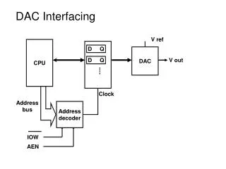
Data Transfer Schemes • The data transfer schemes refers to the method of data transfer between the processor and peripheral devices. • Interface should use a data transfer scheme between IDs. • In a typical microcomputer, data transfer takes place between any two devices: • -microprocessor and memory • -microprocessor and I/O devices • -memory and I/O devices.
An I/O device interface is a circuit betweena device and the interconnection network Provides the means for data transfer andexchange of status and control information Includes data, status, and control registersaccessible with Load and Store instructions Memory-mapped I/O enables software to view these registers as locations in memory I/O Device Interface
Contd. • For example, an I/O device may be slower than the processor due to which , it can not send data to the processor at the expected time. • The µP system designer often face difficulties while interfacing I/O devices and magnetic memories(like floppy or hard disk) to achieve effective data transfer to or from µP. • Several data transfer schemes have been developed to solve the interfacing problem with I/O devices.
Contd. • The data transfer schemes have been broadly classified into the following two categories:
Classification of Data Transfer schemes Data Transfer Schemes Programmed data transfer DMA data transfer Cycle stealing DMA mode Block transfer DMA mode Demand transfer DMA mode Synchronous mode Asynchronous mode Interrupt Driven mode Vectored Interrupts Polled Interrupts Software Polling Hardware Polling Fixed Priority Variable Priority
Programmed Data Transfer • In a programmed data transfer, CPU has to execute program instructions to transfer group of bits from source to destination.
Contd. • Program controlled data transfers can take place under several conditions. They are:
Programmed Data Transfer • The programmed data transfer scheme can be further classified into the following three types: • Synchronous data transfer scheme • Asynchronous data transfer scheme • Interrupt driven data transfer scheme
Synchronous data transfer scheme • Synchronous transfer mean transfers occurring at the same time. • The sender and receiver are synchronized to operate at the same clock speed. • This is preferred when the speeds of both the sender and the receiver match. • The synchronous data transfer scheme can also be implemented with small delay(if the delay is tolerable) after the request has been made.
Asynchronous data transfer scheme • Asynchronous transfer mean transfers taking place at irregular intervals. • When the I/O device speed and µp speed do not match, asynchronous mode may be used. • Data transfer between the microprocessor and the peripherals are primary asynchronous. • In asynchronous data transfer scheme, first the processor sends a request to the device for read/write operation. Then the processor keeps on polling the • status of the device. Once the device is ready, the processor executes a data transfer instruction to complete the process.
Interrupt driven data transfer scheme • The interrupt driven data transfer scheme is the best method of data transfer for effectively utilizing the processor time. • In this scheme, the processor first initiates the I/O device for data transfer. After initiating the device, the processor will continue the execution of instructions in the program. • Also at the end of an instruction the processor will check for a valid interrupt signal. • If there is no interrupt then the processor will continue the execution.
Interrupt driven data transfer scheme • an interrupt is a signal to the processor emitted by hardware or software indicating an event that needs immediate attention
Contd. Execution sequence ISR execution sequence Start ISR Request the device to get ready Save the processor status Find the next instn to execute Execute data transfer instrn Check for interrupt No Restore the processor status Yes Return to the main program Call the ISR corresponding to that interrupt
Types of Interrupts • External interrupts • Internal interrupts • Software interrupts • Hardware interrupts
Contd. • Is a particular instructions that can be inserted into the desired location in the program. • They allow the microprocessor to transfer program control from the main program to the subroutine program