Download
1 / 12
140 likes | 390 Views
HALL EFFECT CIRCUITS ECE001. BHAVYA PURI 10801731 A6802A25. WHAT IS HALL EFFECT. Hall Effect

E N D
HALL EFFECT CIRCUITSECE001 BHAVYA PURI 10801731 A6802A25
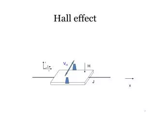
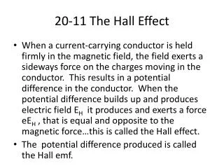
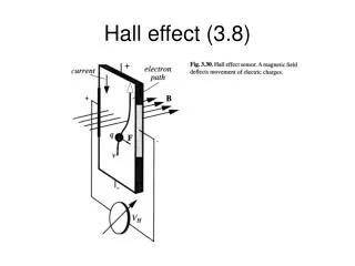
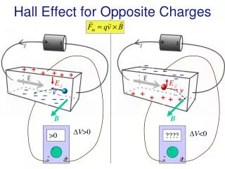
WHAT IS HALL EFFECT • Hall Effect • If an electric current flows through a conductor in a magnetic field, the magnetic field exerts a transverse force on the moving charge carriers which tends to push them to one side of the conductor. This is most evident in a thin flat conductor as illustrated. A buildup of charge at the sides of the conductors will balance this magnetic influence, producing a measurable voltage between the two sides of the conductor. The presence of this measurable transverse voltage is called the Hall effect after E. H. Hall who discovered it in 1879. • Note that the direction of the current I in the diagram is that of conventional current, so that the motion of electrons is in the opposite direction. That further confuses all the "right-hand rule" manipulations
2.HALL VOLTAGE FOR POSITIVE CHARGE CARRIERS • The transverse voltage (Hall effect) measured in a Hall probe has its origin in the magnetic force on a moving charge carrier. • The magnetic force is where is the drift velocity of the charge.
The current expressed in terms of the drift velocity is • where n is the density of charge carriers. • And substituting gives
CHARGE CARRIERS IN THE HALL EFFECT • The Hall effect is a conduction phenomenon which is different for different charge carriers. In most common electrical applications, the conventional current is used partly because it makes no difference whether you consider positive or negative charge to be moving. But the Hall voltage has a different polarity for positive and negative charge carriers, and it has been used to study the details of conduction in semiconductors and other materials which show a combination of negative and positive charge carriers. • The Hall effect can be used to measure the average drift velocity of the charge carriers by mechanically moving the Hall probe at different speeds until the Hall voltage disappears, showing that the charge carriers are now not moving with respect to the magnetic field. Other types of investigations of carrier behavior are studied in the quantum Hall effect.
Motor On A Hall Effect Switch • This is a simple and probably the most reliable motor. • In 1879 Edward Hall placed a thin layer of gold in a strong magnetic field. He connected a battery to the opposite sides of this film and measured the current flowing through it. He discovered that a small voltage appeared across this film. This voltage was proportional to the strength of magnetic field • multiplied by the current. This effect bears his name. • For many years the Hall effect was not used in practical applications because the generated voltage in the gold film was extremely low. However, in the second half of the 20th century the mass production of semiconductor chips started. Chips based on the Hall effect became inexpensive and widely available.
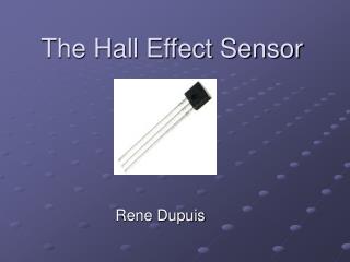
The Hall effect IC (integrated circuit) is a very small chip which includes many transistors. It consists of a thin layer of silicon as a Hall generator (which works better than gold) and several transistor circuits: to amplify the Hall voltage to a necessary level; to trigger output voltage with its growth; and to provide stable work regardless of the power supply voltage changes. The picture below demonstrates the Hall effect IC (between the coin and two power transistors):
The Hall effect IC is a solid state electronic device with no mechanical parts and therefore it is more reliable than a reed switch. To no surprise it is now the most widely used sensor in industrial brushless motors. Normally, however, they include a lot of other components. I tried to design a motor on a Hall effect switch with minimum parts based on the same unified mechanical design and it worked very well. • The Hall effect IC is a unipolar switch. It turns on and off when the South pole of the magnet passes by its branded side. The North pole has no effect on it, unless it approaches from the back side of the Hall IC. This Hall effect IC has a built in voltage regulator and may work in the range from 4.5 to 24V. The Hall effect IC's included in the kit, however, were tested extensively; and I found that most of them start working at 3V. This is a typical Hall effect IC shown from the branded side:
The Hall effect switch output current is not sufficient to power this motor, therefore it also requires a power transistor. You may find information on this component at How It Works: Reed Switch Motor With A Transistor. • This is how this motor works: • 1. When magnet #1 gets close to the Hall IC, the sensor sends a signal to the base of the power transistor. The transistor opens, and allows a bigger collector current to flow through the electromagnet. The electromagnet pushes magnet #3 away.
When the rotor spins away, magnet #1 stops affecting the Hall IC. Since the signal to the base of the power transistor has been removed, it is turned off. This disables the electromagnet. • The rotor continues to spin due to inertia until magnet #2 moves into the working range of the Hall IC. The Hall IC sends a signal to the base of the transistor. The transistor opens, and allows a bigger collector current to flow through the electromagnet. The electromagnet pushes magnet #4 away. This process continues until the power is disconnected.