Download
1 / 17
180 likes | 455 Views
Laser alignment system. Status report. Krzysztof Oliwa Eryk Kielar, Wojciech Wierba, Leszek Zawiejski, INP PAN, Cracow, Poland Wojciech Slominski, Jagiellonian University, Cracow , Poland. FCAL Collaboration Meeting , May 6-7, 200 8, INP PAN - Cracow, Poland.

E N D
Laser alignment system Status report Krzysztof Oliwa Eryk Kielar, Wojciech Wierba, Leszek Zawiejski, INP PAN, Cracow, Poland Wojciech Slominski, Jagiellonian University, Cracow , Poland FCAL Collaboration Meeting, May 6-7, 2008, INP PAN - Cracow, Poland
High precision in luminosity measurement and high accuracy in determination of LumiCal position Single (Left / Right) LumiCal alignment LumiCal IP Outgoing beam LumiCal X, Y position with respect to the incoming beam should be known with accuracy better than ~700 µm (optimal ~100-200 µm) (LumiCal’s will be centered on outgoing beam) min LumiCal Two LumiCal’s (L,R) alignment Distance between two LumiCal’s should be known with accuracy better than ~60-100 µm (14 mrad crossing angle)
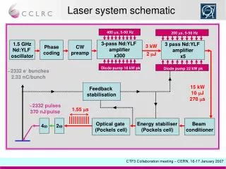
Laser alignment system (LAS): laser beam monitoring with CCD sensor 450 beam spot Laser beam spots on the surface of CCD camera (640 x 480 pixels) (picture from the computer monitor) 00 beam spot • Two laser beams, one perpendicular, second with the • angle of 45˚ to the CCD/CMOS sensor surface, are • used to calculate the position shift\ • The CCD camera and lasers can be fixed to the • LumiCal and beam pipe • Three or more sensors can be used to measure tilt • of each LumiCal • Six (?) laser beams from one to another LumiCal passing inside the ‘carbon support’ pipe can be used : • to measure therelative position shift (the method described above) • the distance between two LumiCal’s (very challenging, not solved yet) • Measurement based on frequency scanning interferometry to measure distance between calorimeters X Z X Z Laser2 Laser1
LAS : laser beam monitoring system with CCD camera The picture on the face of pixel CCD silicon camera Shape of the spots 00 beam spot 450 beam spot 450 beam spot Y X 00 beam spot Pixels saturation - used ND filters
LAS : laboratory setup Present setup – dual laser beam • BW camera DX1-1394a from Kappa company 640 x 480 with Sony ICX424AL sensor 7.4 μm x 7.4 μm unit cell size • Laser module LDM635/1LT from Roithner Lasertechnik • ThorLabs ½” travel translation stage MT3 with micrometers (smallest div. 10 μm) • Neutral density filters ND2 • Renishaw RG24 optical head (0,1 µm resolution) to control movement of the lasers • New support for laser aligments
Results of X & Z position measurements X, Z displacement measurement relative to reference system Xcaland Zcal positions – from improved algorithm for centre beam spotdetermination. x = Xcal - Xtrue displacement (m) : ± 1 m z = Zcal - Ztrue displacement (m) : ± 1.5 m • Laserstable was translated in steps of 50 μm. • The distances Xtrue and Ztrue was measured with Renishaw RG-24 optical head with the resolution of ±0.1 µm
Stability - temperature dependence (current laboratory setup) The temperature dependence of the beam spots position in CCD camera: heating or cooling down environment of the laser system. Cooling down – measurement for each 5 minutes Over the T = 5.2 0 C. Position calculated from algorithm • Insulated heating box . • For each temperature point, the mean position • of the spot centers from multiple measurements • were calculated using improved algorithm 45 degree beam Perpendicular beam T = 34 0 C 45 degree beam Perpendicular beam T=28.8 0 C The relative distance two spots The observed changes on the level ~ 2 m/1 0 C
Temperature stabilization – the small temperature changes (T ~ 0.10 C) 5 minutes measurements: 45 degree laser beam 0 degree laser beam The calculated X,Y positions of both beams - the relative changes are on the level ± 0.3 m Even without temperature influence some effect coming from nature of laser spot and systematic uncertainties in used algorithm can be important The changes in distance betwen spots: on the level ± 0.4 m
Temperature stability > 8 hours measurements : temperature changes within T ~ 0. 1 degree 45 degree beam 0 degree beam The relative distance between laser beams The observed changes in calculated X,Y spots positions are on the level 0.5 m. Contribution from other effects ? • It is necessary to stabilize the temperature of camera • Collimator and laser optics should be improved
Temperature stability > 24 hours measurements : temperature changes within T ~ 0. 2 degree 45 degree beam 0 degree beam The relative distance between laser beams The observed changes in calculated X,Y spots positions are on the level 0.5 m. Contribution from other effects ? • It is necessary to stabilize the temperature of camera • Collimator and laser optics should be improved
LAS development – integration with LDC Beam pipe can be centered on detector axis or on outgoing beam: a different free space for LumiCal Alignment (L/R) measurement based on beam pipeand BPM.s. Alignment two parts (L+R) of LumiCAl • Reflective laser distance measurement – accuracy ~1-5 µm, resolution ~0.1-0.5 µm • Mirrors glued to beam pipe • Calibration of sensors procedure – detector push-pull solution (?) • Calibration of sensors procedure after power fault (?) will be behind BeamCal • Beam pipe (well measured in lab before installing, temperature • and tension sensors for corrections) with installed BPM • Laser beams inside ‘carbon’ pipe (need holes, but possible) – interferometric measurement
LAS development – integration with LDC Proposed method: measurement based on frequency scanning interferometry
Example from MC studies on the internal structure deformation Changes in X,Y and Z positions of the Tungsten and Si sensors layers ideal Z The changes in relative luminosity according to changes in internal structure along Z axis Z dedormation in Z An in X,Y directions Z deformation in X and Y Possible systematic effect on luminosity measurements is expected to be about one order smaller in comparison to possible displacement the Lumical detector as whole but still should be treated carefully as possible significant contribution to total error in luminosity calculation
LAS development – measurement of individual sensor layers Spanned wire alignment Proposed solutions for the onlinemeasurement of the LumiCal sensor planes : Spanned wire alignment : • Active during time slots between trains • Possible interferences with FE electronics • Accuracy up to ~0,5 µm • Quite simple electronics • Need 4 coax cables for each plane Spanned wire going through the holes in sensor planes working as antena and pickup electrodes to measure the position
Capacitive sensors: • - Displacement -> measurnig reactance of the capacitance beetwen central electrode and conducting surface of the target • Central electrode connected to AC source with a controlled frequency (close to 15kHz) • Small distance (up to 1mm) to measuring • Sensivity ~3,5mV / um • Guard rings reduces the edge effects for the sensor electrode
Summary • LAS is very challenging project in respect to the requirements: • precisely positioned Si sensors (inner radius accuracy < ~4 µm), • X & Y alignment with respect to the beam < ~700 µm, • distance between Calorimeters < ~100 µm, tilts < ~10 mrad • The current laboratory prototype : • the accuracy in position measurements are on the level ± 1.0 μm in X,Y and ± 2 µm in Z direction • thermal stability of the prototype is ~1 µm/ºC • The final LAS design will take into account LDC geometry • More work is ongoing on the system development: • alignment of both parts of LumiCal, • positions of the internal sensor layers, • the more compact prototype, • readout electronics for dedicated sensors • and automatic position calculations