Download
1 / 37
370 likes | 544 Views
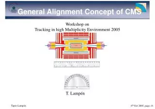
THE CMS ALIGNMENT SYSTEM. Task of the align. system Monitor the position of the m -chambers and the CT detectors with respect to each other. Building blocks: 4 subsystems - Internal tracker align. - Internal muon : barrel and endcap - The link tracker Û muons (3 alignment planes).

E N D
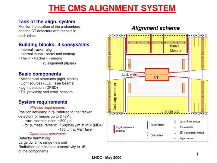
THE CMS ALIGNMENT SYSTEM Task of the align. system Monitor the position of the m-chambers and the CT detectors with respect to each other. Building blocks:4 subsystems - Internal tracker align. - Internal muon : barrel and endcap - The link tracker Û muons (3 alignment planes) Alignment scheme • Basic components • Mechanical structures (rigid, stable) • Light sources (LED, laser beams) • Light detectors (DPSD) • Tilt, proximity and temp. sensors System requirements Physics requirements Position accuracy in rf (referred to the tracker detector) for muons up to 2 TeV : - track reconstruction: ~500 mm - for pt measurement: ~150(350) mm at MB1(MB4) ~150 mm at ME1 layer Operational constraints Detector hermeticity Large dynamic range (few cm) Radiation tolerance and insensitivity to DB of the components LHCC - May 2000
THE CMS ALIGNMENT SYSTEM Alignment scheme LHCC - May 2000
THE CMS ALIGNMENT SYSTEM Alignment scheme LHCC - May 2000
MUON ALIGNMENT SYSTEMORGANIZATION AND PARTICIPANTS Internal Barrel Internal Endcap Link system CERN(CMT) USA: SPAIN: Hungary (Debrecen) : FERMILAB CIEMAT (Madrid) Kossuth L. Univ. North-Eastern Univ. IFCA (Santander) ATOMKI Austria (Vienna) : HEPHY Inst. Fur H. der OAW Pakistan (Islamabad) : Optics Labs. LHCC - May 2000
Link Tracker - Muons Working principle • Translates Tracker co-ordinates (points, f angles) to the ´linking points´ in the external MABs • The tracker co-ords are defined by the internal tracker alignment at the TK ends (TK alignment wheels) • The MAB ´linking points´ serve for Barrel and Endcap connection to the Tracker • Each 1/4 f plane is generated independently. The whole system is constrained at the TK volume • Points (3D co-ords) are measured with laser beams + semitransparent sensors for the co-ords perpendicular to the beams, and by mechanical tubes and proximity sensors for the co-ords along the beams • The f angle is measured at each structure (TK wheel and MABs) by Laser Level units • Measures directly ME1/2 chambers (CSCs crossed by a secondary link line) and the ME1/1 CSC disk (using a ME1/1 transfer platform to bend by 90° the laser beam) LHCC - May 2000
Barrel muon alignment Working principle 36 rigid mechanical structures called MABs are holding TV-cameras (typically 10 cameras/MAB). These cameras are observing LEDs mounted on both sides of the barrel muon chambers ( 40/chamber) and on the so called Z-bars (the reference in Z-direction). A high level of redundancy is achieved by multiple observations and loops which make the system robust and reliable. The barrel system is connected to the TK via linking lines. LHCC - May 2000
Endcap muon alignment Connect Endcap CSCs to Tracker • Tracker co-ordinates (points, f angles) from the MAB modules (via link system) • 6 axial lines (transfer lines) pass through the MABs and run outside each CSC station • Connection between axial lines and SLMs on transfer plates. • Z distance measured by mechanical tubes and optical gap sensors • Radial measurements from transfer plates to CSCs by potentiometers CSCs alignment design • 3 laser lines per CSC station (SLM) are linked to the axial transfer lines: • SLM measures location of CSCs (on 1/6) • SLMs are 60 degrees apart, mount on CSCs at same point on each chamber • Precise location of sensors on CSCs using internal calibration and photogrammetry • Precise relationship of strips, alignment pins, and sensors on CSCs LHCC - May 2000
Fig 2. EMU Transfer-line Schematics Endcap muon alignment: Transfer lines and Z measurements LHCC - May 2000
Endcap muon alignment: SLMs ALIGNMENT SCHEMATICS Transfer Sensor Transfer Laser EMU Transfer line · · M M 1 2 · SLM Laser P 1 Transfer Plate MAB SLM sensor LHC Beam CSC CSC SLM-line 2-D P · 2 sensor Transfer Plate EMU Transfer line Alignment Schematics. Only one transfer laser is shown, at the top-left corner, defining the EMU transfer line. Similarly for the SLM line, only one laser beam, coming from the top is shown. The other laser beams coming from the opposite directions have been omitted for clarity. LHCC - May 2000
Barrel alignment status • Mechanics: MABs and LED holders • Minimal system test • Readout electronics LHCC - May 2000
MAB Modules(External MABs) Barrel cameras Link sensors Endcap transfer sensors LHCC - May 2000
MAB development • Aluminum prototype used for first tests. • New prototype under construction (Portugal) • Glass fiber 1.5 ´ 1 m2 • Study deformations at the junctions (data by June) Þ define final geometry and materials • 3D design of the different MAB structures: most of integration problems (inside the Mu-detector and at boundary region) have been identified. LHCC - May 2000
LED holders in the MB chambers - Four forks /chamber - Each fork instrumented with 10 LED (4/6) - LED positions within the holder: 16 mm (x,y), 60 mm (z) Total number of LED ~ 10000 - Mounting of precalibrated forks and LED driver electronics during chamber assembly at the production sites. - Calibration of each chamber at Cern before installation in the detector Estimated calibration precision: 55-65 mm (x,y) 470 mm (z) LHCC - May 2000
LED Holder mechanical repeatability Deviation wrt to a mean of a series of position-reposition tests LHCC - May 2000
BARREL alignment stand (CERN ISR I4-hall) Layout of the Minimal test of the barrel alignment: disposition of alignment components as for the central muon barrel wheels LHCC - May 2000
Minimal barrel test results: Accurate reconstruction of LED positions with a floating calibrated MAB referenced by external system s(D5) = 18 mm s(D4) = 38 mm s(M5) = 11 mm s(M4) = 25 mm s(G5) = 20 mm s(G4) = 52 mm LHCC - May 2000
Readout electronics Control room • Bla bla... Slow control Ethernet MAB Chamber Slow control for barrel muon chambers Board computer AMPRO Littleboard P5i (PC104 type) 146x203x30 mm3 CAN • 100/166 MHz Pentium* processor • PC/AT compatible system on a single board • Up to 128M bytes onboard DRAM • PC/104 with PCI extension • Floppy, IDE, EPP, Parallel, 4 Serial ports • PCI UltraSCSI • PCI Super VGA LCD/CRT local bus controller • with GUI accelerator • High speed Ethernet LAN interface • Extensive embedded feature set: ruggedized • BIOS, bootable solid state disk, • watchdog timer, powerfail NMI, locking I/O • connectors, Advanced Power Management • Small size +5V only operation, low power • requirement, extended temperature operation I2C Barrel muon chamber slow control unit Temperature Sensors (4 to 16) Z bar - LEDs (0 to 4) MAB - LEDs (0 to 20) Cameras (16 to 24) 4 LED holders (<20 LED-s/holder) LHCC - May 2000
Barrel alignment: summary • Prototypes of components exist: • Mechanical design of LED holders and video cameras is ok • Final MAB design under development • Neutron irradiation of the opto-electronic components up to highest barrel doses (fluences = 2.6 ´1012 n/cm2): ok • Magnetic field tests (up to 1T) of cameras, LED, and board computer prototype: ok • Readout electronics (prod. version) under development • DAQ + Software test version ready • First test of the system concept ok: consistent with expectations • Full simulation of system performance (as for the TDR) LHCC - May 2000
Endcap alignment status • Mechanical progress • Sensor developments • DAQ and software LHCC - May 2000
Mechanical progress and Sensor technology Layout • Most conflicts resolved: • Required some changes to the disk and cart designs • SLM lines change z position due to RPC chambers layout • Mount positions on CSCs defined: Prototype mount plates and towers constructed for ME23/2 chamber • Roughly 50% of transfer plate production drawings finished Sensor development • The SLM design requires up to 10 sensors in line: • ALMY: Semitransparent a-Si sensors (see later) • DCOPS: Digital CCD optical position sensor • 4 linear CCDs mounted in a window frame + cross-hair laser beam • Readout with DSP processor and serial I/O • Good test results on resolution & stability • Radiation test: Test CCDs in 4 MeV proton beam (neutron fluences of 1.3 ´ 1013 n/cm2ÞPresent version of the CCD and readout are acceptable (safety factor ~3) LHCC - May 2000
DCOPS sensor board LHCC - May 2000
DCOPS neutron irradiation LHCC - May 2000
CCDs neutron irradiation LHCC - May 2000
DCOPS neutron irradiation • bbb LHCC - May 2000
Endcap DAQ and Software • DAQ system (C++ in window98 env.) has two branches: DCOPS readout chain: • Line of DCOPS boards read out through serial interface • 1 serial processor / disk (Note that the read-out DAQ will be very much the same for DCOPS and ALMY) HP readout chain: • HP readout unit contains all multiplexers, switches and signal conditioning hardware • 1 HP readout unit /disk • Two steps offline analysis: FLAP (First Level Analysis Program, C++, OO design on UNIX platform ): • Takes raw data from DAQ as input and fits data to find centroid in CCD pixel numbers. • Convers HP DC voltage read out appropiate position and temperature units SLAP (Second Level Analysis Program): • Takes FLAP output as input and converts the CCD centroid pixel numbers to the real space positions using the position calibration constants • .... Design in progress LHCC - May 2000
Link system status • Mechanical progress • Sensor developments (ALMYs and Laser Level) • DAC system and Software LHCC - May 2000
Mechanical progress Layout • Mechanical drawings in the endcap/barrel region (MAB and ME1/2) ready • ME1/1 transfer and mounts on ME1/1 CSCs prototype drawings exits • Re-design of the h= 3 region in accordance with the EE calorimeter support • TK region in standby ... (position and size of passage re-defined for new geometry) • Complete prototypes for the ISR tests (tests of mechanical behaoivor): Laser box, Laser Level, distance meas (mechanical tube + optical and potentiometers), periscope -short size, ~40 cm-, DPSDs mounts, re-positionings platforms . LHCC - May 2000
Sensors develpoment (1) • ALMY: Semitransparent a-Si sensors Performance: Linearity and resolution: 5 mm Sensor fiducilization: ~1 mm (2D configuration) Radiation hardness: - g (CIEMAT) up to 10 Mrad: ok - n (ATOMKI) total fluence 1015 n/cm2: ok - p (24 GeV/c PS CERN) total fluence 1013 n/cm2: sensors still cooling down ... Optical properties: >75 % transmission Serial readout electronics New prototypes development: Stuttgart: succeeded to produce test structures with dark currents as low as required. They proceed now with the fabrication of the first set of complete test sensors with final layout and bonding pads until beginning of July. This effort is carried out -within CMS- by Spain. It is done in collaboration with the MPI (Munich), institute involved in the alignment of the muon chambers of the ATLAS experiment. Minnesota: produced (by Feb 2000) two complete prototypes (with identical geometry as the old EG&G sensors). Their optical and electrical properties have been studied at CIEMAT-Madrid. The electrical test was not satisfactory: the sensors did not show the typical diode curve. Instead, they yield IV curves rather symmetric with respect to the (0,0) point which correspond to two mutually inverted Schottky barriers. This behavior was understood given the high symmetry of the structure (ITO/intrinsic a-Si/ITO) of the prototypes. Two lines of actions have been identified for the new prototypes to be built. The optical test was instead rather satisfactory. The measured transmission for both devices was over 75% and quite flat over the whole working region (wavelength 750-900 nm). New prototypes ( 8 units) will be ready by summer. We will be testing mainly the electrical properties of the junction and charge division between strips, given that the optics is already properly understood. This effort was supported -within CMS- by US and Spain until beginning of 2000. It will continue mainly by Spanish institutes. LHCC - May 2000
Semitransparent aSi:H sensors (ALMY) Thickness aSi £1 mm Thickness electrodes £100 nm Thickness glass substrate 500 mm Number of electrodes 64 horizontal, 64 vertical Active area 20 mm ´ 20 mm Strip pitch 312 mm Low Hall mobility Þ B field insensitive Amorphous Si Þ Rad. hardness Glass substrate Þ Multi-point meas. 19 mm dia. LHCC - May 2000
Sensors develpoment (2) • Laser Level units Consist of: A laser source + a tiltmeter (AGI and AOSI) one or two dimensional Performance: Linearity and resolution: ~10 mrad (independent tilt calibration) Stability of the assembly: <5 mrad Radiation hardness and insesitivity to B: to be tested - From manufacters (AGI): ok up to 10 Mrad g doses insensitive to uniform fields, and ok up to 80 gauss/mm LHCC - May 2000
After stabilization = 0.6 rad TOTAL: 6.7 days Tiltmeter (AGI-756) calibration: linearity, resolution and stability V(mV) = 460.35 mV/mrad (mrad) - 16.39 mV After stabilization = 1.9 rad TOTAL: 6.7 days LHCC - May 2000
_Y_position = 4.4 rad _AGI1= 4.1 rad _Y_position = 5.6 rad _AGI1= 5.4 rad Laser level: calibration and mechanical stability LHCC - May 2000
DAQ and Control system + Software DAC configuration: Level 1: includes sensors and local electronics boards(LEB) • LEB: microcontroler with flash program memory and data memory + CAN controler chip • The microcontroler is equiped with: ADC convertors to handle the signal coming from the diferent sensors used (temperatutre, DPSD, tiltmeters,..), a serial port, timers for signal generation and several digital I/O ports to control the 2D position sensors. It will perform basic treatment of the signals (center of gravity, gaussian fits..) • At the moment each LEB handles up to 4? sensors (any type) sitting at < xx m from the actual devices. Level 2: comunication via CAN bus between L1 and industrial PC • Each LEB comunicates via CAN bus protocol with the PC using a Main Controler Interface (a CAN controler board with two ports) placed in the PC • PC for data storage and processing Level 3: comunication via Ethernet between align. PC and Detector Control System (DCS) Software: Level 1: LabView (programming graphic platform) for data acquisition and control. Fully developed for system tests Level 2: CMS OO code for optical alignment (COCOA). Simulation and reconstruction package.(ISR version available) LHCC - May 2000
Planned activities (Y2000) • Complete test with Link system, Barrel and Endcap alignment (ISR-I4) • The installation of components and DAQ started last week (May 10th) • ~ 5 weeks for individual calibration of parts • First common data taking by ~ 20 June. • The full setup will stay in place up to end of the year • EDR foreseen for October • Endorse the general scheme • LED holders for the DT chambers first to go into production LHCC - May 2000