Download
1 / 50
1.38k likes | 2.74k Views
Transmission Media. Lecture 4. Overview. Transmission m edia Transmission m edia classification Transmission Media characteristics and design specifications Guided and Unguided media Wireless Transmission Frequencies Antennas Wireless Propagation. Transmission Media.

E N D
Transmission Media Lecture 4
Overview • Transmission media • Transmission media classification • Transmission Media characteristics and design specifications • Guided and Unguided media • Wireless Transmission Frequencies • Antennas • Wireless Propagation
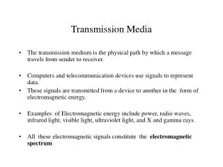
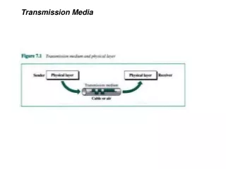
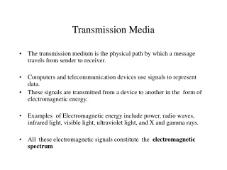
Transmission Media • The transmission medium is the physical path by which a message travels from sender to receiver. • Computers and telecommunication devices use signals to represent data. • These signals are transmitted from a device to another in the form of electromagnetic energy. • Examples of Electromagnetic energy include power, radio waves, infrared light, visible light, ultraviolet light, and X and gamma rays. • All these electromagnetic signals constitute the electromagnetic spectrum
Electromagnetic Spectrum • Not all portion of the spectrum are currently usable for telecommunications • Each portion of the spectrum requires a particular transmission medium
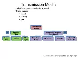
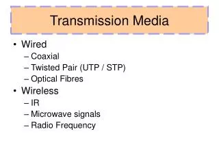
Transmission Media Classification Guided media, which are those that provide a conduit from one device to another. Examples: twisted-pair, coaxial cable, optical fiber. Unguided media (or wireless communication) transport electromagnetic waves without using a physical conductor. Instead, signals are broadcast through air (or, in a few cases, water), and thus are available to anyone who has a device capable of receiving them.
Transmission Media Classification Characteristics and quality determined by medium and signal For guided, the medium is more important For unguided, the bandwidth produced by the antenna is more important Key concerns are data rate and distance
Transmission Media Classification • One key property of signals transmitted by antenna is directionality. • In general, signals at lower frequencies are omnidirectional; that is, the signal propagates in all directions from the antenna. • At higher frequencies, it is possible to focus the signal into a directional beam
Transmission Media Classification Atmosphere and Outer space Signals of low frequency (like voice signals) are generally transmitted as current over metal cables. It is not possible to transmit visible light over metal cables, for this class of signals is necessary to use a different media, for example fiber-optic cable.
Design Factors for Transmission Media • Bandwidth: All other factors remaining constant, the greater the bandwidth of a signal, the higher the data rate that can be achieved. • Transmission impairments. Limit the distance a signal can travel. • Interference: Competing signals in overlapping frequency bands can distort or wipe out a signal. • Number of receivers: Each attachment introduces some attenuation and distortion, limiting distance and/or data rate.
Frequency Range Typical Attenuation Typical Delay Repeater Spacing Twisted pair (with loading) 0 to 3.5 kHz 0.2 dB/km @ 1 kHz 50 µs/km 2 km Twisted pairs (multi-pair cables) 0 to 1 MHz 0.7 dB/km @ 1 kHz 5 µs/km 2 km Coaxial cable 0 to 500 MHz 7 dB/km @ 10 MHz 4 µs/km 1 to 9 km Optical fiber 186 to 370 THz 0.2 to 0.5 dB/km 5 µs/km 40 km Transmission Characteristics of Guided Media
Twisted Pair • Twisted pair is the least expensive and most widely used guided transmission medium. • Consists of two insulated copper wires arranged in a regular spiral pattern • A wire pair acts as a single communication link • Pairs are bundled together into a cable • Most commonly used in the telephone network and for communications within buildings
Twisted Pair-Transmission Characteristics Susceptible to interference and noise
(Impairments) Near End Crosstalk (TP) • Coupling of signal from one pair of conductors to another occurs when transmit signal entering the link couples back to the receiving pair – (near transmitted signal is picked up by near receiving pair)
Signal Power Relationships (TP Characteristics) Fig. illustrates the relationship between NEXT loss and insertion loss at system A. A transmitted signal from system B, with a transmitted signal power of Pt is received at A with a reduced signal power of Pr. At the same time, system A is transmitting to signal B, and we assume that the transmission is at the same transmit signal power of Pt. Due to crosstalk, a certain level of signal from A's transmitter is induced on the receive wire pair at A with a power level of Pc; this is the crosstalk signal. Clearly, we need to have Pr > Pc to be able to intelligibly receive the intended signal, and the greater the difference between Pr and Pc, the better. Unlike insertion loss, NEXT loss does not vary as a function of the length of the link
UTP Connectors The most common UTP connector is RJ45 (RJ stands for Registered Jack).
Applications • Twisted-pair cables are used in telephones lines to provide voice and data channels. • The DSL lines that are used by the telephone companies to provide high data rate connections also use the high-bandwidth capability of unshielded twisted-pair cables. • Local area networks, such as 10Base-T and 100Base-T, also used UTP cables.
Coaxial Cable • Coaxial cable can be used over longer distances and support more stations on a shared line than twisted pair. • It consists of a hollow outer cylindrical conductor that surrounds a single inner wire conductor • It is a versatile transmission medium used in a wide variety of applications • It is used for TV distribution, long distance telephone transmission and LANs
Coaxial Cable Outer plastic sheath Woven copper shield Inner dielectric insulator Copper core Coaxial cables have numerous uses; they are used for transmitting video as well as radio signals and for high-speed internet connections. This type of cable can be made out of a number of different materials depending on the frequency and impedance of the device with which it is being used.
BNC Connectors - To connect coaxial cable to devices, it is necessary to use coaxial connectors. The most common type of connector is the Bayone-Neill-Concelman, or BNC, connectors. There are three types: The BNC connector, the BNC T connector, the BNC terminator. Applications include cable TV networks, and some traditional Ethernet LANs like 10Base-2, or 10-Base5.
Coaxial Cable • Advantages : • Coaxial cable can support greater cable lengths between network devices than twisted pair cable. • Thick coaxial cable has an extra protective plastic cover that help keep moisture away.Disadvantages : • It does not bend easily and is difficult to install. Common applications of coaxial cable include video and CATV distribution, RF and microwave transmission, and computer and instrumentation data connections
Optical Fiber An optical fiber (or optical fibre) is a flexible, transparent fiber made of high quality extruded glass (silica) or plastic, slightly thicker than a human hair. It can function as a waveguide, or “light pipe” to transmit light between the two ends of the fiber. • Optical fiber is a thin flexible medium capable of guiding an optical ray. • Various glasses and plastics can be used to make optical fibers • It has a cylindrical shape with three sections – core, cladding, jacket • It is being widely used in long distance telecommunications • Performance, price and advantages have made it popular to use
Optical Fiber - Benefits • Greater capacity • Data rates of hundreds of Gbps • Smaller size and lighter weight • Considerably thinner than coaxial or twisted pair cable • Reduces structural support requirements • Lower attenuation • Electromagnetic isolation • Not vulnerable to interference, impulse noise, or crosstalk • High degree of security from eavesdropping • Greater repeater spacing • Lower cost and fewer sources of error
Optical Fiber-Transmission Characteristics • Uses total internal reflection to transmit light • Effectively acts as wave guide for 1014 to 1015 Hz (this covers portions of infrared & visible spectra) • Light sources used: • Light Emitting Diode (LED) • Cheaper, operates over a greater temperature range, lasts longer • Injection Laser Diode (ILD) • More efficient, has greater data rates • Has a relationship among wavelength, type of transmission and achievable data rate
Propagation Modes (Types of Optical Fiber ) • Current technology supports two modes for propagating light along optical channels, each requiring fiber with different physical characteristics: • Multimode and Single Mode. • Multimode, in turn, can be implemented in two forms: step-index or graded index.
Optical Fiber Transmission Modes Light from a source enters the cylindrical glass or plastic core. Rays at shallow angles are reflected and propagated along the fiber; other rays are absorbed by the surrounding material. This form of propagation is called step-indexmultimode, referring to the variety of angles that reflect When the fiber core radius is reduced, fewer angles will reflect. By reducing the radius of the core to the order of a wavelength, only a single angle or mode can pass: the axial ray. This single-mode propagation provides superior performance for the following reason. Because there is a single transmission path with single-mode transmission, the distortion found in multimode cannot occur. Single-mode is typically used for long-distance applications Finally, by varying the index of refraction of the core, a third type of transmission, known as graded-index multimode, is possible. This type is intermediate between the other two in characteristics. The higher refractive index (discussed subsequently) at the center makes the light rays moving down the axis advance more slowly than those near the cladding
Propagation Modes (Types of Optical Fiber ) • Multimode: In this case multiple beams from a light source move through the core in different paths. • In multimode step-index fiber, the density of the core remains constant from the center to the edges. A beam of light moves through this constant density in a straight line until it reaches the interface of the core and cladding. At the interface there is an abrupt change to a lower density that alters the angle of the beam’s motion. • In a multimode graded-index fiber the density is highest at the center of the core and decreases gradually to its lowest at the edge.
Frequency Utilization for Fiber Applications In optical fiber, based on the attenuation characteristics of the medium and on properties of light sources and receivers, four transmission windows are appropriate. The four transmission windows are in the infrared portion of the frequency spectrum, below the visible-light portion, which is 400 to 700 nm. The loss is lower at higher wavelengths, allowing greater data rates over longer distances
Fiber-optic cable connectors The subscriber channel (SC) connector is used in cable TV. It uses a push/pull locking system. The straight-tip (ST) connector is used for connecting cable to networking devices. MT-RJ is a new connector with the same size as RJ45.
Electromagnetic Spectrum for Telecommunications Electromagnetic Spectrum for Telecommunications
An antenna (or aerial) is an electrical device which converts electric power into radio waves, and vice versa Antennas • Electrical conductors used to radiate or collect electromagnetic energy • Same antenna is often used for both purposes Antennas are essential components of all equipment that uses radio. They are used in systems such as radio broadcasting, broadcast television, two-way radio, communications receivers, radar, cell phones, and satellite communications, as well as other devices such as garage door openers, wireless microphones, bluetooth enabled devices, wireless computer networks, baby monitors, and RFID tags on merchandise.
Radiation Pattern Characterize the performance of an antenna • Power radiated in all directions • Does not perform equally well in all directions • An isotropic antenna is a point in space that radiates power • In all directions equally • with a spherical radiation pattern
Parabolic Reflective Antenna used in terrestrial microwave and satellite applications
Antenna Gain • Measure of the directionality of an antenna • Power output in particular direction verses that produced by an isotropic antenna • Measured in decibels (dB) • Results in loss in power in another direction • Effective area relates to physical size and shape Antenna gain is a key performance figure which combines the antenna's directivity and electrical efficiency. As a transmitting antenna, the figure describes how well the antenna converts input power into radio waves headed in a specified direction. As a receiving antenna, the figure describes how well the antenna converts radio waves arriving from a specified direction into electrical power A plot of the gain as a function of direction is called the radiation pattern.
Terrestrial Microwave A system, method, technology, or service, such as Multichannel Multipoint Distribution Service, that utilizes microwave line of sight communications between sending and receiving units located on the ground or on towers, as opposed to a sender and/or receiver antenna being located on a communications satellite. Used, for instance, for telephone, TV, and/or data services. Also called Terrestrial Microwave radio.
Terrestrial Microwave Applications • Used for long haul telecommunications, short point-to-point links between buildings and cellular systems • Used for both voice and TV transmission • Fewer repeaters but requires line of sight transmission • 1-40GHz frequencies, with higher frequencies having higher data rates • Main source of loss is attenuation caused mostly by distance, rainfall and interference
Satellite Microwave • A communication satellite is in effect a microwave relay station • Used to link two or more ground stations • Receives on one frequency, amplifies or repeats signal and transmits on another frequency • Frequency bands are called transponder channels • Requires geo-stationary orbit • Rotation match occurs at a height of 35,863km at the equator • Need to be spaced at least 3° - 4° apart to avoid interfering with each other • Spacing limits the number of possible satellites
Satellite Microwave Applications • Uses: Private business networks • Satellite providers can divide capacity into channels to Lease to individual business users Television distribution • Programs are transmitted to the satellite then broadcast down to a number of stations which then distributes the programs to individual viewers • Direct Broadcast Satellite (DBS) transmits video signals directly to the home user Global positioning • Navstar Global Positioning System (GPS)
Transmission Characteristics • The optimum frequency range for satellite transmission is 1 to 10 GHz • Lower has significant noise from natural sources • Higher is attenuated by atmospheric absorption and precipitation • Satellites use a frequency bandwidth range of 5.925 to 6.425 GHz from earth to satellite (uplink) and a range of 3.7 to 4.2 GHz from satellite to earth (downlink) • This is referred to as the 4/6-GHz band • Because of saturation the 12/14-GHz band has been developed (uplink: 14 - 14.5 GHz; downlink: 11.7 - 12.2 GH
Broadcast Radio • Radiois the term used to encompass frequencies in the range of 3kHz to 300GHz • Broadcast radio (30MHz - 1GHz) covers • FM radio • UHF and VHF television • data networking applications • Omnidirectional • Limited to line of sight • Suffers from multipath interference • reflections from land, water, man-made objects The principal difference between broadcast radio and microwave is that the former is omnidirectional and the latter is directional. Thus broadcast radio does not require dish-shaped antennas, and the antennas need not be rigidly mounted to a precise alignment.
Infrared • Achieved using transceivers that modulate noncoherent infrared light • Transceivers must be within line of sight of each other directly or via reflection • Does not penetrate walls • No licenses required • No frequency allocation issues • Typical uses: • TV remote control One important difference between infrared and microwave transmission is that the former does not penetrate walls. Thus the security and interference problems encountered in microwave systems are not present. Furthermore, there is no frequency allocation issue with infrared, because no licensing is required.
Summary • Guided and Unguided Media • Advantages and disadvantages some of the media (TP, STP, UTP, Coaxial, Fiber) • Design factor of the underlying media • Antennas