Download
1 / 22
250 likes | 449 Views
Transmission Media. CPSC 441 Tutorial – April 2, 2012 TA: Ruiting zhou. Does not use telephone infrastructure Instead uses cable TV infrastructure It is integrated into the cable TV infrastructure analogously to DSL which uses the existing telephone network.

E N D
Transmission Media CPSC 441 Tutorial – April 2, 2012 TA:Ruitingzhou
Does not use telephone infrastructure Instead uses cable TV infrastructure It is integrated into the cable TV infrastructure analogously to DSL which uses the existing telephone network. DSL: Digital subscriber line, provide internet access by transmitting digital data over the wires of a local telephone network HFC: hybrid fiber coax Asymmetric: up to 30 Mbps downstream, 2 Mbps upstream network of cable and fiber attaches homes to ISP router homes share access to router unlike DSL, which has dedicated access Residential access: cable modems
Residential access: cable modems tap, a device that monitors data on a computer network
Cable Network Architecture: Overview Typically 500 to 5,000 homes cable headend home cable distribution network (simplified) cable head-end: the facility at a local cable TV office that originates and communicates cable TV services and cable modem services to subscribers
server(s) Cable Network Architecture: Overview cable headend home cable distribution network
Cable Network Architecture: Overview cable headend home cable distribution network (simplified)
C O N T R O L D A T A D A T A V I D E O V I D E O V I D E O V I D E O V I D E O V I D E O 5 6 7 8 9 1 2 3 4 Channels Cable Network Architecture: Overview FDM Frequency-division multiplexing (more shortly): cable headend home cable distribution network
ONT ONT ONT Fiber to the Home opticalfibers Internet • Optical links from central office to the home • Two competing optical technologies: • Passive Optical network (PON) : uses electrically powered switching equipment, such as a router or a switch aggregator, to manage signal distribution and direct signals to specific customers • Active Optical Network (AON): uses optical splitters to separate and collect optical signals as they move through the network • Much higher Internet rates; fiber also carries television and phone services opticalfiber OLT optical splitter central office
Typical home network components: DSL or cable modem router/firewall/NAT Ethernet wireless access point Home networks wireless laptops to/from cable headend cable modem router/ firewall wireless access point Ethernet
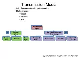
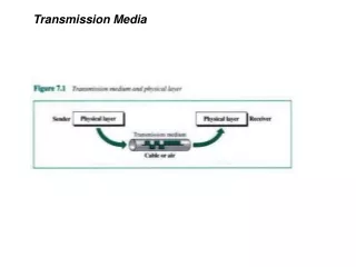
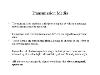
Bit: propagates betweentransmitter/rcvr pairs physical link: what lies between transmitter & receiver guided media: signals propagate in solid media: copper, fiber, coax unguided media: signals propagate freely, e.g., radio Twisted Pair (TP) two insulated copper wires Category 3: traditional phone wires, 10 Mbps Ethernet Category 5: 100 Mbps Ethernet Physical Media
Coaxial cable: two concentric copper conductors bidirectional baseband: single channel on cable legacy Ethernet broadband: multiple channels on cable HFC Physical Media: coax, fiber Fiber optic cable: • glass fiber carrying light pulses, each pulse a bit • high-speed operation: • high-speed point-to-point transmission (e.g., 10’s-100’s Gbps) • low error rate: repeaters spaced far apart ; immune to electromagnetic noise
signal carried in electromagnetic spectrum no physical “wire” bidirectional propagation environment effects: reflection obstruction by objects interference Physical media: radio Radio link types: • terrestrial microwave • e.g. up to 45 Mbps channels • LAN (e.g., WiFi) • 11 Mbps, 54 Mbps • wide-area (e.g., cellular) • 3G cellular: ~ 1 Mbps • satellite • Kbps to 45 Mbps channel (or multiple smaller channels) • 270 msec end-end delay • geosynchronous versus low altitude
Analog and Digital Transmissions use of both analog and digital transmissions for a computer to computer call. Conversion is done by the modems and codecs.
Data Encoding Techniques • Digital Data, Analog Signals [modem] • Digital Data, Digital Signals [wired LAN] • Analog Data, Digital Signals [codec] • Frequency Division Multiplexing (FDM) • Wave Division Multiplexing (WDM) [fiber] • Time Division Multiplexing (TDM) • Pulse Code Modulation (PCM) [T1] • Delta Modulation
Digital Data, Digital Signals[the technique used in a number of LANs] • Digital signal – is a sequence of discrete, discontinuous voltage pulses. • Bit duration : the time it takes for the transmitter to emit the bit. • Issues • Bit timing • Recovery from signal • Noise immunity
Binary Encoding • NRZ (non-return to zero) • NRZI (NRZ inverted) • Manchester (used by IEEE 802.3, 10 Mbps Ethernet)
Bits 0 0 1 0 1 1 1 1 0 1 0 0 0 0 1 0 NRZ Non-Return to Zero (NRZ) • Encode binary data onto signals • e.g., 0 as low signal and 1 as high signal • voltage does not return to zero between bits • known as Non-Return to Zero (NRZ)
sender’s clock receiver’s clock Problem: Consecutive 1s or 0s • Low signal (0) may be interpreted as no signal • High signal (1) leads to baseline wander • Unable to recover clock • sender’s and receiver’s clock have to be precisely synchronized • receiver resynchronizes on each signal transition • clock drift in long periods without transition
NRZI • Non-Return to Zero Inverted (NRZI) • has a transition at a clock boundary if the bit being transmitted is “1” • Stay at current signal (maintain voltage level) to encode/ transmit a “zero” • Solves the problem of consecutive ones (shifts to 0s) • NRZI can have long series of zeros , still unable to recover clock
Manchester • Manchester (in IEEE 802.3 – 10 Mbps Ethernet) • Split cycle into two parts • Send high--low for “1”, low--high for “0” • Transmit XOR of NRZ encoded data and the clock • Clock signal can be recovered from the encoded data. • Only 50% efficient (1/2 bit per transition): double the transmission rate.
Bits 0 0 1 0 1 1 1 1 0 1 0 0 0 0 1 0 NRZ Clock Manchester NRZI Different Encoding Schemes
Reference • CPSC 441 Chapter 1 Slides 16-28 • http://en.wikipedia.org/wiki/File:NRZI_example.png • CS716 Advanced Computer Networks by Dr. Amir Qayyum