Download

1 / 60
1.76k likes | 4.7k Views
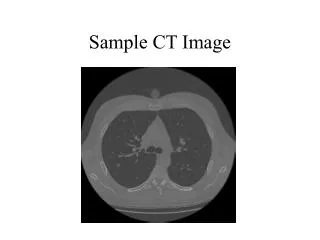
Image post processing in CT. Modern CT scanners produce a set of contiguous sectional images Combining the sections produces a volumetric data set of voxels (pixels) Volumetric techniques visualise volumetric data as a whole. Isotropic voxels.

E N D
Modern CT scanners produce a set of contiguous sectional images • Combining the sections produces a volumetric data set of voxels (pixels) • Volumetric techniques visualise volumetric data as a whole
Isotropic voxels • isotropic data (ie, voxels have the same depth, length, and height)
View projections • The volume data are three dimensional and cannot be viewed directly in a single 2-D image • Therefore we need to project these data on a projection plane, in a way similar to a film in a camera
View projections • Every point in the volume data is transformed to a point on the projection plane (flat, 2-D image) • Projection ray starts from projection centre (viewpoint) and passes through the point to be projected • The intersection point of this ray with the projection plane is the projected position • The viewpoint is usually located at a certain distance along a line perpendicular to the centre of the projection plane.
Parallel projection • The view point is at infinity • Faster to perform • Relative sizes and angles are preserved in the final image • Perspective projection • Objects are projected to a single point behind the projection plane • Causes distortion (objects closer appear larger), resembles real life • Precludes accurate direct measurements • Stereoscopic projection • Two perspectives with partial shift to the left and right give the perception of depth
2D Display tools - cine • Cine display • Helps viewing a large number of sections in any plane • More precise view of complex anatomy (ie. vessels that get in and out of the same section) • Increased conspicuity of lesions • Basic viewing method
Stacking the original images and cutting through them in any plane, that is from a given angle of view a plane is reconstructed in a defined depth of the volume Cor- and sag- simply represent voxel stacks Oblique and curved MPRs need interpolation Plane selected interactively on reference image of several types Cut line in any plane and of variable thickness 2D Display tools – MPRs Multiplanar reconctructions
2D Display tools MPRs • Thin and overlapping original images create less artefacts along the z-axis thus producing better MPRs • The resulting image retains the resolution of the original images provided that acquisition is isotropic • MPRs from 0.5mm sections maintain the same resolution as the original section thus eliminating the need for scanning in different planes (dose reduction)
2D Display tools thick MPRs • Generally MPRs are the size of a voxel • Selecting thickness > original improves SNR • By increasing the thickness the mean value of >1 adjacent voxels perpendicular to the cut line is calculated • Retain in plane image resolution
2D Display tools – cMPRs • Curved MPRs may be made along the course of a structure
2D Display tools – cMPRs • Need workstation supporting function • Structures that cross multiple planes coming in and out of the reference planes • Semi-automated • Vessel tracking • Best way of estimating vessel stenosis in the presence of dense plaques
2D Display tools ray sum projection • Similar to a very thick MRR • Looks like a plain –XR • You may choose to include a certain range of intensities only • Exclusion of bones produces DSA like images
Artifacts • The closest to the transverse plane the better the quality • Thin sections • Overlapping sections
3D Display tools • Maximun Intensity Projection MIP • Minimum Intensity Projection minIP • Surface Shaded Display SSD • only one layer of voxels is used for visualization (~10% of data) • Volume Rendering techniques VRT • Tissue transition projection TTP • all the data in volume are used
MIP • The highest attenuation value of the voxels on each view throughout the volume is projected onto the 2D image. • White cubes represent voxels with the highest attenuation value; black cubes represent voxels with the lowest attenuation value
MIP - minIP • MIP images are created by a series of parallel rays projected through the volume data • Only the highest (or lowest, minIP) attenuation voxels become part of the image (>95% of data lost) • Depth information is lost and it is not possible to tell whether a structure is located in the front or back on the basis of a single MIP image • They produce angiographic type images and help follow the course of a structure • Cardiac pulsation - nearby lung • Rosary like vessels • Emphysema like changes
MIPs • Retain the maximum intensity values so include the bones rather than structures like enhanced vessels • May separate calcified plaques from vessel lumen • May show even small vessels • Image background depends on the intensities of the adjacent structures. Selection of the highest pixel value increases also the background mean of the image, particularly in enhancing structures such as the kidney and liver, thereby decreasing the visibility of vessels in these structures • Removing structures that enhance improves structure to background contrast ratio • Selecting small thickness improves structure to background contrast ratio (thin-MIPs) • Segmentation
thin-slab MIPs • The attenuation value of the voxels on each view throughout the volume is projected onto the 2D image. • White cubes represent voxels with the highest attenuation value; black cubes represent voxels with the lowest attenuation value
thin-slab MIPs • Use of multiple overlapping thin MIPs eliminates spatial relation limitations • More than one planes • Retain spatial resolution • Increasing thickness of the axial sections reduces small vessel contrast due to partial volume averaging • MIP contrast does not change with different slab thickness
Right renal artery stenosis (arrow). Overlapping, limited volume maximum intensity projection rendering • At least two orthogonal planes are critical to the high-resolution interrogation of small structures such as the renal arteries, avoiding overlap and the overestimation of stenosis
minIP • The lowest attenuation value of the voxels on each view throughout the volume is projected onto the 2D image. • White cubes represent voxels with the highest attenuation value; black cubes represent voxels with the lowest attenuation value Multi–Detector Row CT and Postprocessing Techniques in the Assessment of Diffuse Lung Disease. RadioGraphics, 25, 1639-1652
minIP • Good for the tracheobronchial tree • Shows distribution of diffuse lung disease • Better if surroundings are soft tissue density (mediastinum, consolidation) • Increasing slab thickness affects small airway conspicuity • Overlying air exclusion
Surface Shaded Display, SSD • Each voxel within the data set is determined to be a part of or not a part of the object of interest, usually by comparing the voxel intensity to some threshold value • Display a subset of volumetric data including voxels within a defined range of attenuation values to determine surface • Upper and lower thresholds are defined and from a chosen angle of view the first layer of voxels with an attenuation within the defined parameters is displayed • In SSD pixels of the structure with intensities within the threshold values are represented with maximum opacity while pixels outside the threshold are assigned zero opacity and do not contribute to the image
SSD • As all pixels have the same opacity only the surface of the structure is shown in SSD and information about the attenuation of a structure is lost completely • An attenuation range for reconstruction can be provided and the computer will generate the image • Manually drawing around the boundaries of a structure and the computer will connect these areas automatically • As the surface of the structure is shaded there is no ‘see through’ and > 90% of data lost
Shaded Surface Display (SSD) 150HU 100HU 200HU
average VSD VR MinIP MIP VIP
Segmentation • Segmentation - • division of an image into multiple areas or objects (called primitives) with distinct features (organ, tumor) • To display specific structures present in the volume they first need to be identified
The attenuation value is a good indicator of the presence of a structure • Thresholding - selection of the voxels with intensity within a particular range of intensities • Thresholding may be used alone or as the basis of further processing in the volume data set • Using a seed function the segmented data may be deselected, shrunken or expanded
Threshold selection • The best value is the one that represents a structure in its real size • It lies between the intensity values of the structure and those of its surroundings • Approximately 10% less than the structure values • Only structures > than the slice thickness are represented normal size • High slice thickness results in wrong representation and partial volume artifacts • In bones it may produce holes where there is thinning • It may cause pseudo narrowing or cut offs
Low threshold • More voxels included increasing the apparent size and volume, but • allows for smaller structures to be seen • offsets partial volume effects allowing for realistic representation of small structures • Creates flying – floating pixels due to noise • Includes other enhancing structures that get above the threshold
High threshold • Fewer voxels included decreasing apparent size and volume • No floating pixels and overlapping structures • In osteoporotic bones (low bone threshold) avoiding adjacent structures will produce multiple holes
Segmentation tools • Editing • Region growing • Dilatation / erosion • Closing functions (removal of holes) • Removal of flying pixels (floaters) • Watershed algorithms • Automated bone removal • Automated volume analysis
Editing used to remove structures which may interfere with visualization of the intravascular contrast need for data editing varies with the specific clinical application and the 3-D rendering technique absolutely essential with MIP, not so with SSD, VR. Manual Editing Editing section to section is time consuming 3-D slab editing more efficient Needs projection from a view point with no overlap of structures to be removed and remain
Extracting geometry from medical images Stack of images (1mm) Contour extraction by segmentation Sample points on extracted geometry Alfio Quarteroni Rio de Janeiro 6-7 may 2008
Editing • Automated Editing • Automated editing applications are available for specific domains such as the lung, abdomen, liver. Interactivity by real time rendering allows very fast and effective manual editing with simple editing tools. • Cut-Planes • Real-time volume rendering with clip plane editing provides a flexible means of interactively editing the actual 3-D image. User prescribed clip-planes can be positioned at any orientation or depth within volume.
Region growing Connectivity algorithms Selects pixels similar to the pixel of reference Sections or slabs Pseudo bridging of different areas Automatic separation with threshold change Manual separation
Dilatation / erosion Remove or add pixels in the structure surface depending on the shape Remove pseudo bridges
Closing functions Removal of holes within the structure
Watershed algorithms Separation of structures connected with bridges by defining the lowest intensity value in the bridge
Applications • Used mainly in skeletal and vessel representation • Interactive navigation in virtual endoscopy • Images can be viewed from any view point and complex anatomic relations can be solved
Volume rendering techniques (VRT) • Images of surfaces or semitransparent structures • Render the entire volume of data rather than just surfaces or MIP voxels, and so potentially conveys more information than a surface model. • Sum the contributions of each voxel along a line from the viewer's eye through the data set. Much more powerful computers necessary for reasonable speed • Combine SSD and MIP and apply ranges of opacity values to intensity values • Basically select several groups of voxels according to their attenuation in HU and assign them a color and a so-called opacity • Segment data based on voxel attenuation
VRT controls • Window width and level controls • Opacity • Opacity refers to the degree which structures close to the user obscure structures which are further away. • Opacity values can be varied between 0% and 100% and produce an opacity histogram • change the apparent size of objects. Higher opacity values make objects appear larger, while lower opacity values make them appear smaller • opacity of 50% gave the most accurate measurements of vessel diameter • Several colors may be attributed to different opacities/intensities producing color maps of different organs
Brightness • The brightness can be varied from 0 to 100%. Brightness affects the appearance of the image, but does not affect accuracy - unlike opacity, it does not alter the apparent diameter of rendered structures. Brightness settings are largely subjective based on the preferences of the individual user. We have found that a setting of 100% works well for nearly all applications
SSD VIP
Artefacts • Venetian blind artefact • Less prone to pseudo narrowing than SSD • Noise may produce artefacts in the surface of structures
VRT Applications • CTA • Lumen and calcified plaques • Color mapping for arteries and veins • Viewing thrombus in aneurysms • Segmentation of overlapping structures • Musculoskeletal • View comminuted fractures (acetabulum) • Operation planning for minimal intervention • Less holes than SSD • Allows viewing of bones, tendons and skin surface • Intervertebral discs