Download
1 / 29
290 likes | 445 Views
SSD readout upgrade . M . LeVine, R. Scheetz -- BNL Ch. Renard , S. Bouvier -- Subatech J . Thomas -- LBNL. Readout components. Ladder cards . RDO (1 of 8). Slave FPGA. VME FPGA. VME interface. Fiber links. Slave FPGA. Slave FPGA. DAQ PC. Master FPGA. DAQ interface.

E N D
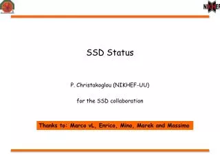
SSD readout upgrade M. LeVine, R. Scheetz -- BNL Ch. Renard, S. Bouvier -- Subatech J. Thomas -- LBNL
Readout components Ladder cards RDO (1 of 8) Slave FPGA VME FPGA VME interface Fiber links Slave FPGA Slave FPGA DAQ PC Master FPGA DAQ interface DDL SlaveFPGA TRG interface SlaveFPGA South platform VME crate Outer support cone DAQ room
Prototype ladder card (outer side) Debug connector Flex cable connectors to ladder modules Optical transceiver
Interposer • FPGA layout error • Choice of redoing the PCB • or designing an interposer between the PCB and FPGA • Interposer design, fabrication, and assembly: 6 months • Present status: installed and operational
Debug cards (Subatech) • USB port • JTAG (configuration) • JTAG (slow controls)
Ladder card commissioning • Using debug card • JTAG FPGA configuration • JTAG slow controls • USB simple protocol • Using fake static source • Map analog response • ADCs and level shifting circuitry • Verify packing of ADC data working correctly
Mapping analog response • Software • Python script driving • Multiple .exe (C code) • Time to map response for 1 ADC: 30 sec • Time to map all 16 ADCs: 20 minutes • Disconnect/connect flex cable • Basis for future slow controls software • SC uses JTAG header on debug card • Will be replaced by fiber protocol
16 20 40 MHz 50 MHz Verification of packing code USB output USB output • USB output for ADC data • Install USB spy at output of FIFO 5 MHz 80 MHz module 16 bit width4words temp adc 12bit 16 bit serial output X16 FIFO serializer to fiber register 2 JTAG TDOs 80 MHz 5 MHz module Write enable:true on 10 clocks only adc 12bit 16 bit serial output
Analog response • Non-linear behavior of N-face needs to be understood • Discovered we are sensitive to PS fluctuations via DAC • Will be separately regulated in production version
Optical xcvr Optical xcvr Optical xcvr 241 241 241 241 241 124 124 124 124 124 SIU 40mm x 160mm Slave FPGA 484 FBGA Slave FPGA 484 FBGA Slave FPGA 484 FBGA Slave FPGA 484 FBGA Slave FPGA 484 FBGA Master FPGA VME FPGA EPCS4 EPCS4 EPCS4 EPCS4 EPCS4 Master EEPROM SIU connectors RDO proposed layout X X Optical xcvr GBIC Reset PB Reboot PB Optical xcvr Optical xcvr Slave EEPROM Keep top layer clear for LVDS serial lanes (master to/from each slave) PS header VME EEPROM Address SW 1 Address SW 2 VME driver VME driver VME driver VME driver VME P2 connector (TRG: rows A,C) VME P1 connector
Reset PB Reboot PB LEMO connector Optical xcvr 241 124 Slave FPGA 484 FBGA EPCS4 QRDO layout Test header (32 signals) X USB conn X FT245R USB 9.1 MHz oscillator PS header Slave EEPROM EPCS16 DC regulator 1.2V 2.5V 3.3V +5V external pwriinput VME P1 connector +5V, GND only
QRDO commissioning • Orsay USB protocol implemented • Message layer on top of byte pipe • Goal: replace VME (4-byte messages) • Problems – • Bad synthesis by Synopsys tool !! • Now resolved • Message protocol working
USB message protocol 4-byte write 6-bit subaddress used for register addressing 4-byte read
Integration of ladder card/QRDO • Generate test patterns on ladder card • Spy on incoming data via fiber with logic analyzer
ADC data received in QRDO DREADY: ADC/STATUS WORD1: Synch Birds-eye view Zoom in on data phase Test pattern as sent (almost)
Status words received in QRDO WordValueComment (from Table 52, master document) 0 07000 configured, OK, serdes clock used 1 04000 deserializerlock OK 2 00000 (no optical transceiver problems) 3 05000 usb present, debug present 4 00000 5 00000 6 01000 7 00000 ladder 0 (not yet assigned by QRDO) serial #1 (agrees with hardware assignment on board)
Master FPGA development (CR) • Original plan for communication • 5 High speed serial lanes • 5 slaves master • As implemented by Altera • Requires more PLLs than available • CR implemented his own serial receivers • Share common PLL • Validation of new scheme in simulation • In progress • See next slides
RDO roadmap • Slave FPGA – code completed • VME FPGA – code completed • Master (TRG/DAQ) FPGA • In late stages of simulation @ Subatech • PCB layout expected to start 12/11 • Assemble prototypes 3/12
Summary of present status • Ladder card • 3 prototypes functional • Analog behavior characterized • Data packing verified • Beginning to look at exported data • QRDO • Message protocol working in USB • Fiber functional • Still a work in progress
Status (cont’d) • RDO • Layout will begin after • master FPGA simulation is complete • and QRDO debugging completed • DAQ PC • Delivered • 2 DRORCs installed
Comments • We were delayed 6 months due to ladder card layout error and subsequent fix with interposer. • We have had working ladder cards only since June, 2011 • Amazing progress since then