Download
1 / 21
210 likes | 295 Views
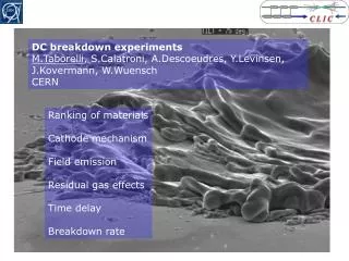
Breakdown experiments. CLIC09 workshop 15.10.2009 Jan Kovermann. Outline. 1. The quantitative approach to high gradients, an introduction 2. Which diagnostic methods are used? 3. Overview of measurable parameters 4. Results from comparative RF and DC breakdown studies

E N D
Breakdown experiments CLIC09 workshop 15.10.2009 Jan Kovermann
Outline 1. The quantitative approach to high gradients, an introduction 2. Which diagnostic methods are used? 3. Overview of measurable parameters 4. Results from comparative RF and DC breakdown studies 5. Details from optical breakdown spectroscopy 6. A proposal for RF breakdown detection 7. The DC breakdown movie 8. Summary
The quantitative approach to high gradients DC measurements High-power scaling laws (RF and materials) Breakdown diagnostics RF measurements Comprehensive RF design Breakdown simulation
The quantitative approach to high gradients • Breakdown source identification Plasma composition simulation and mat.sci. input Plasma size/position simulation and design input Plasma parameters simulation input Spectroscopy BREAKDOWN DIAGNOSTICS RF measurements, FC, XRAY simulation and design input • Machine protection • Conditioning Missing energy ? OTR in nominal pulses simulation and machine parameter input SEM simulation and design input
The connection between simulation and experiment • Emitted currents • Dark current spectrum • OTR • X-rays • Trigger mechanism • Missing energy • Breakdown rate • Ion currents • Fowler-Nordheim distribution Plasma characteristics -Time structure -Physical dimension (imaging) -Ion species (opt. spectroscopy) -Ion currents -Vacuum behaviour Surfaces -Crater morphology -Material diagnostics -Fatigue process
RF and DC diagnostics: some results RF DC OTR (Cu), no BD Cu interband transition (@2.1eV) spectrum Opt. BD spectroscopy Cu I (7.7eV), Cu II (20eV), Cu III (36eV ) ions
RF and DC diagnostics: some results • Spectrum typical for OTR in Cu (interband transition @ 2.1eV) • Beta measurements possible close to the breakdown limit (~105) • OTR sometimes seems to rise before a breakdown • Oxide layers suppress OTR • An estimation of the energy absorbed by electrons in 30GHz structures: 0.1MW @ 14MW RF input power OTR (Cu), no BD • found very little traces of O,H,C,S probably no contribution to breakdown physics in this sample • Estimated temperature from two-line-method: 1-5eV, but Cu III (T>36eV) seen, plasma is a non-LTE plasma! • Intensity waveform for different lines highly non-reproducible (clusters? Different plasma? just geometry?) Opt. BD spectroscopy
RF and DC additional diagnostics RF DC RF (I,Q), Xray, FC @30GHz Current, voltage and delay ? SEM of single breakdowns SEM of single breakdowns
RF and DC diagnostics: BDs are never the same • BDs are very fast (~ns) transient phenomena • BD parameters change over orders of magnitude (e.g. dark current vs. BD current) • BDs are never the same (in RF!) • BDs affect S-parameters (RF) / current and voltage (DC) • random BD current emission (RF) • working on BD-plane formalism for position dependent missing E calculation • optimization of DC setup for fast transients ongoing • development of high dynamic range diagnostic tools (LogAmps etc.) • fast single-shot multi-channel equipment necessary 30GHz speedbump structure
Optical spectroscopy in RF and DC RF DC CERN DC test stand, 6kV DC, OFE Cu sample, 300MV/m surface field SLAC C10 (vg 1.35) structure in ASTA, running at 100MV/m (@48MW), 200ns pulse length
RF and DC BD spectroscopy in detail TypicalCu-plasmaspectrumfor RF and DC, but thereis a problem in the RF spectrum… CuII ???
RF and DC BD spectroscopy in detail … stainlesssteel! Looks like a BD betweencoppergasketandflange (confirmedrecentlyby SLAC).
RF and DC BD spectroscopy in detail Unfortunatelythisis not a pure Cu-BD spectrumanymore (thereisliterature on StStarcweldingdiagnostics, tobechecked)… Cu I temperatureis ~1-3eV depending on linepairs
RF and DC BD spectroscopy in detail • I youcan‘tbeatit, useit! • RF structures are getting more and more complex, not only in terms of geometry, they might contain one day: • New and alternative structurematerials (e.g. CuZr) • Surfacetreatmentandcoatings (e.g. oxidelayers, NEG) • Brazingalloys (e.g. Ag) • Joints andflanges (e.g. StSt, Al) • Damping material (e.g. SiC) • Impuritiesfromproductionandhandling (e.g. dust & dirt)
RF and DC BD spectroscopy in detail Proposal: (Simplified) spectroscopysystemasstandarddiagnostictoolforfuturestructureteststo save time oftremblinguncertantybeforeyoucutthestructure… SurprisinglytheintensityratioofCulinesdoes not changefrom BD to BD, still lookingfor power or pulse lengthdependency…
RF and DC BD spectroscopy in detail Time resolvedspectroscopyofselectedlines in RF (SLAC C10@100MV/m, 200ns) 200ns RF pulse • Initial peaksimilarfor all Cuspecies • Hightdensityand/or Stark/Zeeman effects • White background in spectra T [ns] T [ns] T [ns] T [ns]
RF faraday cup measurements • High currents (5V in 50Ohms, 100mA, 50ns) of electrons hit the FC in each BD event, X-rays are produced by these electrons (30GHz CERN speedbump structure) • FC covers 1/200 of solid angle • approx. 10E13 electrons per BD • X-rays pass vacuum window and Al-foils • at least 10keV to be detectable, • for 10E13 electrons dissipated energy • is around 20mJ • X-rays pass 14mm Cu and 5mm Fe • at least 100keV to be detectable, • for 10E13 electrons dissipated energy • is around 180mJ • In total: • ~200mJ • Very similar to measured missing Energy in RF, but no direct correlation! X-rays Electronsfrom BD
Breakdown detection for CLIC accelerating structures RF diagnostics spin-off • Breakdown detection using pairs of Rogowski-coils: • + easy suppression of main beam signal • + simple electronics • + no reference needed • + can resolve dark current and breakdown current • + radiation hard • + cheap feed-throughs • needs space between structures • beam impedance matching necessary First test with one coil in 30GHz test stand DiffAmp Breakdown current volts volts volts Main beam time time time
RF diagnostics spin-off And how (cheap) it looks like doing the first tests… But now coming back to DC again!
DC breakdown The motion picture TIP Featuring: DC breakdown, 12kV, OFE Copper, 20um gap (500MV/m). Storyline: Capacitor is discharged through the sparc, but the PSU stays connected with high impedance for seconds... SAMPLE
Summary • Breakdown diagnostics offer a new way of approaching the understanding of the breakdown mechanism and its possible feedback to high gradient designs • The experimentsgiveinputto breakdown simulation (plasmaand transient behavior) • Breakdown detectionmethodsbesides RF signalsandfaradaycupweredeveloped (whichareunderconsiderationfor CLIC now) • Fast diagnosticsforabnormalstructure BD behaviorhavebeenpresentedand will beimplemented in structureteststands THANK YOU!