Download
1 / 47
490 likes | 687 Views
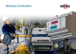
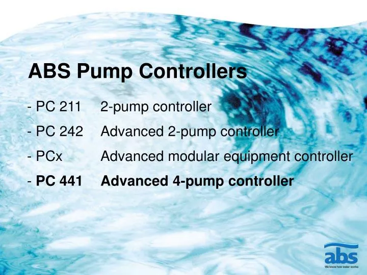
ABS Pump Controllers. - PC 211 2-pump controller PC 242 Advanced 2-pump controller PCx Advanced modular equipment controller PC 441 Advanced 4-pump controller. ABS Advanced Modular Pump Controller PC 441.

E N D
ABS Pump Controllers - PC 211 2-pump controller PC 242 Advanced 2-pump controller PCx Advanced modular equipment controller PC 441 Advanced 4-pump controller
ABS Advanced Modular Pump Controller PC 441 Control and monitoring for up to 4 pumps and the rest of the equipment in the station
Application areas • Network pumping stations • Terminal pumping stations
Benefits Quick and easy to install, set-up and operate Many control functions to reduce number of service visits Many control functions to reduce energy consumption Complete surveillance of pumps and station Robust and reliable hardware & software
Benefits Modular pump controller for up to 4 pumps Basically the same control functions as in PC 242 but for up to 4-pumps Can run and control the station without an operator interface Set-up wizard Advanced pump capacity calculation 16 Digital inputs, 8 Digital outputs, 5 Analogue inputs and 2 Analogue outputs Can be fitted with pump monitoring units
How it worksPC441 Pump Controller Com port for Laptop connection 2 Analogue outputs Internal Bus Com port forModem connection 8 Digital outputs Internal bus indication Power indication Power connection 16 Digital inputs Alarm indication 5 Analogue inputs
How it worksCA511 Graphical operator interface GraphicalDisplay Alpha/NumericKeyboard Power indication Alarm indication Display menu buttons Menu navigationbuttons
How it worksCA441 Di monitoring module One unit for up to 4-pumps or one module per pump: 4 Di 4 Di0 Do Not available 0 Ai Not available Dimension: 35x82 mm Digital input voltage: 5–24 VDC Leakage sensor: Limit: 50 kohm
How it worksCA442 Temp. monitoring module One unit for up to 4-pumps or one module per pump: 4 Di/Ai 4 Klixon/PTC/Pt1000 Do Not available When one unit is used per pump, the Ain 4 can be used to connect a vibration sensor via 4-20 mA Dimension: 35x82 mm Digital in voltage: 5–24 VDC Digital in Resistance: 5 kohm PTC limit: 3 kohm Analogue in resolution: 10 bits
How it worksCA443 Pump and Supply monitoring module • One module per pump: • 6 Ai 3 Voltage inputs 3 Current inputs • 0 Di Not available 0 Do Not available • Dimension: 69x82 mm • Voltage 3 phase: 0-400 VAC • Current 3-phase: 0-5 AC • Measured and calculated parameters: • - Voltage 3 phase • - Current 3-phase • - Energy consumption • - Cos phi • - Over/under voltage • Phase unbalance/loss- Wrong rotation • Frequency readout (nice to have)
How it worksSystem overview CA511 Operator interface CAN-Bus for Internal communication PC441 Pump Controller
How it worksSystem overview, standard alarm monitoring CA511 Operator interface CAN-Bus for Internal communication CA441 DI monitoring module (4 inputs) CA442 Temp. monitoring module (4 inputs) PC441 Pump Controller
How it worksSystem overview, standard alarm monitoring incl. Amp and Voltage CA511 Operator interface CAN-Bus for Internal communication CA441 DI monitoring module (4 inputs) PC441 Pump Controller CA442 Temp. monitoring module (4 inputs) CA443 Voltage, current and power monitoring of 3 phases
How it worksSystem overview, advanced monitoring of DI, temp. amp. and voltage per pump CA511 Operator interface CAN-Bus for Internal communication CA441 DI monitoring module (4 inputs) PC441 Pump Controller CA442 Temp. monitoring module (4 inputs) CA443 Voltage, current and power monitoring of 3 phases
How it worksLevel sensing by hydrostatic level sensor • Long cleaning/maintenance intervals • Easy setting of start & stop points HSC2 HSR
How it worksStarting of Pumps & Mixer Voltage output from PC441 Soft Starter Y/D DOL
How it worksUser interface • Easy to use without prior training • Full picture of station status at a glance • View Status Of Station & Pumps • Change Settings • Manual Control Of Pumps • View & Acknowledge Alarms
How it worksPump control Start P2 Start P1 Stop P1 & P2 Common or separate P1 P2 • Individual start & stop levels with delays • Optimal setting for each type of pump pit • Avoid water hammer • Save hydraulic & electrical network
How it worksPump control Start P2 Start P1 Stop P1 & P2 Common or separate P1 P2 • Random start levels • Avoid fat build-up • Reduce smell • Prolong life of station andits components
How it worksPump control Start P2 Start P1 Stop P1 & P2 Common or separate P1 P2 • Ratio starting(Running hours spread with ratio between pumps e.g. 9 to 1) • Jog run of spare pump • Spare pump in good condition when main pump breaks • Pump that has a tendency toblock can run more often
How it works Pump control Start P2 Start P1 Stop P1 & P2 Common or separate P1 P2 • Exercise run • Avoid pumps clogging if unused for long time • Avoid unnecessary damage to lip seals etc if pumps are unused for a long time
How it works Pump control Start P2 Start P1 Stop P1 & P2 Common or separate P1 P2 • Tariff control • Lower energy costs • Empty pump stationbefore “rush hours” • More even flow to treatment plant
How it works Pump control Start P2 Start P1 Stop P1 & P2 Common or separate P1 P2 • Start/stop on inflow rate change • Avoid flooding • Avoid peak flow tothe treatment plant Start on m/minlevel change Stop on m/minlevel change
How it worksMixer Control • Reduced need for cleaning by tankering truck • Reduce risk of blockage (Distribute solids pumping over the pumping period) • Reduce smell • Reduce forming of corrosive and toxic gases (Hydrogen Sulphide H²S) • Saving energy compared to other methods P1 P2
How it worksMixer Control No Pump is running Interval running of Mixer Level in Mixer running window • Maintain mixing with energy saving Start P2 Start P1 Mixer running window Stop P1 & P2 P1 P2
How it worksMixer Control No Pump is running Mixer stopped Level above Mixer running window • Avoid wasting energy due to large volume Start P2 Start P1 Mixer running window Stop P1 & P2 P1 P2
How it worksMixer Control Pump running Mixer running Level in Mixer running window • Max mixing during pumping Start P2 Start P1 Mixer running window Stop P1 & P2 P1 P2
How it worksMixer Control Pump running Mixer stopped Level below Mixer running window • Avoid pump cavitation at low level Start P2 Start P1 Level below Mixer running window Mixer running window Stop P1 & P2 P1 P2
How it worksPump Surveillance Pump overheat protection • Protect winding insulation from melting Bi-metal (klixon), PTC or Pt100 sensors
How it worksPump Surveillance Pump leakage indication (DI) • Early warning of moisture accumulation in inspection chamber of motor & indication if mechanical seal change needed, before pump gets damaged Ω Conductive measurement of moisture or change of resistance in oil, when water is penetrating through damaged seals
How it worksPump Surveillance Pump dry run protection • Protect pump from being damaged Voltage Current cos φ Water Voltage Current cos φ Dry run
How it worksPump Surveillance Pump overload protection Overload Nominal current Measuring of motor current Remote reset from AquaWeb Emulation of motor protection relay in software Reset Motor protector
How it worksPump Surveillance Motor Current L1 L2 L3 +Get start confirmation +Amp-meter not needed in panel +Protect pump from over current +Dry run protection 0-25 A ac 4-20 mA dc
How it works Pump Surveillance • Pump capacity • Avoid wasting energy using pumps with degraded efficiency • Service pump before breakdown • Service can be planned to be performed at normal working hours • No external flow meterrequired l/s €/m3 kWh m3
How it worksStation Surveillance High float +Get alarm if level sensor or pumps fails +Check level sensor OK +Back-up run of pump(s)
How it worksStation Surveillance Overflow +Report to authorities +Collect data for planning of maintenance & upgrading
How it works Station Surveillance AquaWeb Indication from door or light 1. Man on site . • Hold alarms at visit • Increased safety • Notification of intrusion Local sound notification after delay to reset 2. 3. If no reset,alarm is sent to central server
How it works Station Surveillance Start P2 Start P1 Stop P1 & P2 Common or separate P1 P2 • Inflow & outflow calculation • Collect data for planning ofmaintenance & upgrading Outflow Inflow
How it works Station Surveillance • Energy • Collect data for planning ofmaintenance & upgrading
How it works Station Surveillance • Rain • Collect data for planning ofmaintenance & upgrading • Have proof for abnormal rain intensity
How it works Logging • Collect data for planning ofmaintenance & upgrading
How it works Transfer of logged values to Central Server AquaWeb • Central storage of logged values • Data to base investments & upgrading decisions on GPRS
How it works Alarm Logging • Local storage of alarm history
How it works Alarm transfer direct to operaters mobile • Faster alarm response SMS alarm Alarm to Mobile or Central Server
How it works Alarm transfer to AquaWeb AquaWeb • Faster alarm response • Central storage of alarms for audits GPRS
Summary Designed for use in municipal wastewater pumping networks and to give optimum functionality in each type of standard pumping station. All ABS long experience of how to run and maintain a pumping station to obtain the lowest possible Life Cycle Cost is integrated in the controller functionality.