Download
1 / 59
720 likes | 1.14k Views
Lecture 1. TE-306 DIGITAL COMMUNICATIONS. Dr. Rashid Saleem. This course is designed to prepare students for engineering work in the industry and for advanced graduate work in the area of digital communications. The course covers concepts and useful tools for design

E N D
Lecture 1 TE-306DIGITAL COMMUNICATIONS Dr. Rashid Saleem
This course is designed to prepare students for engineering work in the industry and for advanced graduate work in the area of digital communications. The course covers concepts and useful tools for design and performance analysis of transmitters and receivers in the physical layer of a communication system. Course Objectives
Scope of the course • Communication is a process by which information is exchanged between individuals through a common system of symbols, signs, or behavior • Communication systems are reliable, economical and efficient means of communications such as • public switched telephone network (PSTN) • mobile telephone communication (GSM, 3G, ...) • broadcast radio or television • navigation systems, ... • The course is aiming at introducing fundamental issues in designing a (digital) communication system
Scope of the course ... • Example of a (digital) communication systems: Cellular wireless communication systems BS Base Station (BS) UE UE UE User Equipment (UE)
Digital Communications: Fundamentals and Applications, B.Sklar, Prentice Hall, 2nded, 2001. First Chapter of the book is available at: http: //vig.pearsoned.com/samplechapter/0130847887.pdf Text
Communication Systems, 3rd or 4th Ed., Simon Haykin, John Wiley & Sons Communication Systems Engineering, 2nd Edition, Prentice Hall, 2001. Digital Communications, Fourth Edition, J.G. Proakis, McGraw Hill, 2000. Analog and Digital Communication Systems, Leaon W. Couch II, 6thedition, Prentice Hall, 2001. Modern Digital and Analog Communication Systems, B. P. Lathi, 3rd Ed. Oxford Univ. Press 1998. Lecture slides (ppt, pdf) Laboratory syllabus Set of exercises and formulae Home assignments and solutions References
Required Signals and Systems Recommended Probability and Stochastic Processes Pre-requisites
Digital communication system • Important features of a DCS: • Transmitter sends a waveform from a finite set of possible waveforms during a limited time • Channel distorts, attenuates the transmitted signal and adds noise to it. • Receiver decides which waveform was transmitted from the noisy received signal • Probability of erroneous decision is an important measure for the system performance
Digital versus analog • Advantages of digital communications: • Regenerator receiver • Different kinds of digital signal are treated identically. Original pulse Regenerated pulse Propagation distance Voice Data A bit is a bit! Media
Communication Main purpose of communication is to transfer information from a source to a recipient via a channel or a medium. Basic block diagram of a communication system:
Modes of Communication • Broadcasting • It involves the use of a single powerful transmitter and numerous receivers. • Here information-bearing signals flow in one direction • Point-to-point communication • Communication process takes place over a link between a single transmitter and a receiver. • In this case, there is usually a bidirectional flow of information-bearing signals, which require the use of a transmitter and receiver at each end of the link.
Communication • Communication is a process of conveying messages at distance. • If the distance involved is beyond direct communication, then communication engineering comes into picture. • The branch of engineering which deals with communication system is known as Telecommunication Engineering. • In telecommunication, a physical message, such as sound, word, picture, etc., is converted into an electrical message called signal and this electrical signal is conveyed at a distant place through some media, where it is reconverted into the physical message.
Communication • Thus, a communication system has three basic components: • (a) Transmitter • (b) Transmission media • (c) Receiver Physical message Physical message Communication medium Transmitter Receiver Source Source Electrical Communication System
Communication Processes The generation of a message signal: voice, music, picture, or computer data. The description of that message signal with a certain measure of precision, by a set of symbols: electrical, aural, or visual. The encoding of these symbols in a form that is suitable for transmission over a physical medium of interest. The transmission of the encoded symbols to the desired destination. The decoding and reproduction of the original symbols. The re-creation of the original message signal, with a definable degradation in quality; the degradation is caused by imperfections in the system.
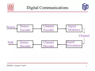
Communication System Communication Process Source of Information Transmitter Receiver User of Information Message Signal Estimate of message Signal Channel Transmitted Signal Received Signal Elements of a Communication system
Estimate of message signal Source of Information Message Signal User of information Source encoder Source decoder Digital Communication Process Estimate of Source code word Source code word Channel encoder Channel decoder Receiver Transmitter Estimate of channel code word Channel code word Modulator Demodulator Channel Waveform Received Signal
DCS – A Brief Description Source: analog or digital Transmitter: transducer, amplifier, modulator, oscillator, power amplifier, antenna Channel: cable, optical fiber, free space etc. Receiver: antenna, amplifier, demodulator, oscillator, power amplifier, transducer Recipient: person, (loud) speaker, computer
DCS – A Brief Description • Types of information • Voice, data, video, music, email etc. • Types of communication systems • Public Switched Telephone Network (voice, fax, modem) • Satellite systems Radio • TV broadcasting Cellular phones • Computer networks (LANs, WANs, WLANs)
Information Representation Communication system converts information into electrical electromagnetic/optical signals appropriate for the transmission medium. Analog systems convert analog message into signals that can propagate through the channel. Digital systems convert bits (digits, symbols) into signals Computers naturally generate information as characters/bits Most information can be converted into bits Analog signals converted to bits by sampling and quantizing (A/D conversion)
Why digital? Digital techniques need to distinguish between discrete symbols allowing regeneration versus amplification Good processing techniques are available for digital signals, such as medium. Data compression (or source coding) Error Correction (or channel coding) (A/D conversion) Equalization Security (encryption, privacy) Easy to mix signals and data using digital techniques Digital circuits are more reliable and can be produced at a low cost.
Why Digital Communication System? • When an ideal binary digital pulse propagates along a transmission line, the shape of the waveform is affected by two basic mechanisms: • All transmission lines and circuits have some nonideal frequency transfer function of the medium and there is a distorting effect on the ideal pulse. • Unwanted electrical noise or other interference further distorts the pulse waveform.
Why Digital Communication System? • Both of these mechanisms cause the pulse shape to degrade as a function of line length or media length. • During the time that the transmitted pulse can still be reliably identified, the pulse is amplified by a digital amplifier that recovers its original ideal shape.
Why Digital Communication System? • The pulse is thus “reborn” or regenerated. • Circuits that perform this function at regular intervals along a transmission system are called regenerative repeaters. • Digital circuits are less subject to distortion and interference than are analog circuits.
Why Digital Communication System? • In digital communication system, two state operation (fully on or fully off) facilitates signal regeneration and thus prevent noise and other disturbances from accumulating in transmission. • With digital techniques, extremely low error rates producing high fidelity is possible through error detection and correction.
Communication Systems Information Source Transmitter Channel Receiver Information Destination Keypad Speakers Brain IP Packet GSM-style RF Vocal Tract SONET Router Wireless RF Acoustic Fiber FM Detector Ears Photo Diode ATM.25 Packet Brain Router POTS Analog Communications: Information is encoded in a continuous amplitude, continuous time signal. Digital Communications: Information is encoded into a discrete time sequence with a quantized alphabet.
Basic Signal Processing Functions • Formatting and source coding • Baseband signaling • Band pass signaling • Equalization • Channel coding • Multiplexing and multiple access • Spreading • Encryption • Synchronization
Signal Flow and Signal Processing Steps in DC • Upper block • Format • Source encode • Encrypt • Channel encode multiplex • Pulse modulate • Bandpass modulate • Frequency spread • Multiple access Denote signal transformation from source to transmitter
Signal Flow and Signal Processing Steps in DC Lower block Multiple access Frequency despread Demodulate & sample Detect Demultiplex Channel decode Decrypt Source decode Format Denote signal transformation From receiver to the sink
Signal Flow and Signal Processing Steps in DC • Modulate and demodulate/detect blocks together are called a modem. • Modem often encompasses several of the signal processing steps; • When this the case, the modem can be thought as the “brain” of the system. • The transmitter and receiver can be thought of as the “muscles” of the system
Signal Flow and Signal Processing Steps in DC • For wireless applications, the transmitter consists of a frequency up-conversion stage to a radio frequency (RF), a high-power amplifier, and an antenna. • The receiver portion consists of an antenna and a low-noise amplifier (LNA). • Frequency down-conversion is performed in the front end of the receiver and/or the demodulator.
Signal Flow and Signal Processing Steps in DC • Figure illustrates a kind of reciprocity between the blocks in the upper transmitter part of the figure and those in the lower part. • Trans side • The input information at source is converted to binary digits (bits); the bits are then grouped to form digital message or message symbols. • Each such symbol (mi , where I = 1, …, M) can be regarded as member of a finite alphabet set containing M members.
Signal Flow and Signal Processing Steps in DC • Thus, for M = 2, the message symbol mi is binary (just a single bit). • For systems that use channel coding (error coding), a sequence of message symbols becomes transferred to a sequence of channel symbols (code symbols), where each symbol is denoted by ui. • Because a message symbol or a channel symbol can consist of a single bit or grouping of bits, a sequence of such symbols is also described as bit stream.
Signal Flow and Signal Processing Steps in DC • Only formatting, modulation, demodulation/detection, and synchronization are essential for a DCS. • Formatting transforms the source information into bits and up to pulse modulation block, the information remains in the form of a bit stream. • Modulation is the process by which message symbols or channel symbols are converted to waveforms that are compatible with the requirements imposed by the transmission channel.
Signal Flow and Signal Processing Steps in DC • Pulse modulation is an essential step because each symbol to be transmitted must first be transformed form a binary representation to a baseband waveform. • The terms baseband refers to a signal whose spectrum extends from (or near) dc up to some finite value, usually less than a few megahertz. • The pulse-modulation block usually includes filtering or minimizing the transmission bandwidth. • When pulse modulation is applied to binary symbols, the resulting binary waveform is called a pulse-code-modulation (PCM) waveform called line codes.
Signal Flow and Signal Processing Steps in DC • After pulse modulation, each message symbol or channel symbol takes the form of a baseband waveform gi(t), I = 1, …, M. • For an application involving RF transmission, the next step is bandpass modulation; the baseband waveform gt(t) is frequency translated by a carrier wave to a frequency si(t), that is much larger than the spectral contents of gi(t). • As si(t) propagates over the channel, it is impacted by the channel characteristics, described in terms of the channel’s impulse response hc(t).
Signal Flow and Signal Processing Steps in DC • Receive Side • At various points along the signal route, additive random noise distorts the received signal r(t), so that its reception must be termed as a corrupted version of the signal si(t) that was launched at the receiver. • The received signal r(t) can be expressed as • r(t) = si(t) * hc(t) + n(t) I = 1, …, M
Signal Flow and Signal Processing Steps in DC • In the reverse direction, the receiver front end and/or demodulator provides frequency down conversion for each bandpass waveform r(t). • The demodulator restores r(t) to an optimally shaped baseband pulse z(t) in preparation for detection. • Several filters associate with receiver and demodulator, filter the baseband pulse to remove unwanted high frequency terms, and shape the pulse by the channel.
Signal Flow and Signal Processing Steps in DC • Equalization can be described as the filtering option that is used in or after the demodulatorn to reverse any degrading effects on the signal that were caused by the channel. • Equalization becomes essential whenever the impulse response of the channel, hc(t), is so poor that the received signal is badly distorted.
Communication Channels Channel: The medium linking the transmitter and receiver. It is ALWAYS analog in nature. That is every communication system is more or less ANALOG. • Channel Types • Wire/line Channels: use a conductive medium to direct transmitted energy to the receiver: • Copper wire for telephones, xDSL • Fiber optic cable • Aluminum interconnects for ICs • Wireless Channels: Uses an open propagation medium • RF for cell phones • Underwater acoustic ducts for whales
Performance Metrics Analog Communication Systems Metric is fidelity: want SNR typically used as performance metric Digital Communication Systems Metrics are data rate (R bps) and probability of bit error Symbols already known at the receiver Without noise/distortion/sync. problem, we will never make bit errors
Main Points Transmitters modulate analog messages or bits in case of a DCS for transmission over a channel. Receivers recreate signals or bits from received signal (mitigate channel effects) Performance metric for analog systems is fidelity, for digital it is the bit rate and error probability.
Channel Impairments As a transmitted signal propagates it loses fidelity in a number of ways. This loss of fidelity makes the received signal look very different from the transmitted signal. Additive Noise: Thermal noise, multi-transmitter interference Noise + Transmitter Receiver Multiplicative Noise: Rayleigh Fading Noise x Transmitter Receiver Convolution Noise: time-delay multipath, reverberation (echo) Noise Transmitter Receiver
Objective Information Source Transmitter Channel Receiver Information Destination 1. How to design 2. Taking into account • 3. That will provide a system that is: • Reliable: information received is what was sent • Efficient: Not wasteful of time, power or spectrum • Simple: economical for H/W and S/W and usually Robust