Download
1 / 49
550 likes | 1.12k Views
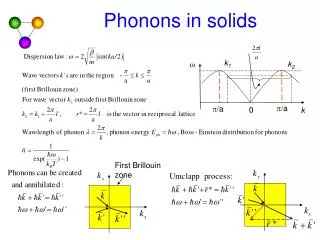
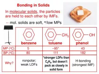
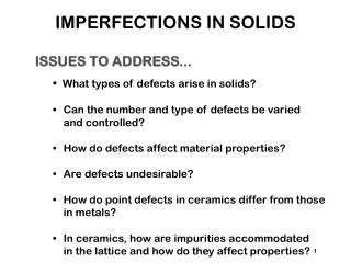
IMPERFECTIONS IN SOLIDS. ISSUES TO ADDRESS. • What types of defects arise in solids? Can the number and type of defects be varied and controlled? How do defects affect material properties? Are defects undesirable? How do point defects in ceramics differ from those in metals?

E N D
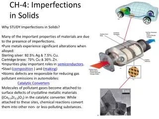
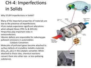
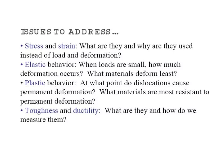
IMPERFECTIONS IN SOLIDS ISSUES TO ADDRESS... • • What types of defects arise in solids? • Can the number and type of defects be varied • and controlled? • How do defects affect material properties? • Are defects undesirable? • How do point defects in ceramics differ from those • in metals? • In ceramics, how are impurities accommodated • in the lattice and how do they affect properties?
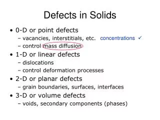
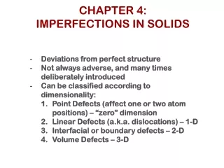
TYPES OF IMPERFECTIONS • Vacancy atoms • Interstitial atoms • Substitutional atoms Point defects Line defects Area defects • Dislocations • Grain Boundaries
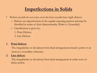
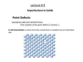
POINT DEFECTS • Vacancies: -vacant atomic sites in a structure. • Self-Interstitials: -"extra" atoms positioned between atomic sites.
OBSERVING EQUIL. VACANCY CONC. • Low energy electron microscope view of a (110) surface of NiAl. • Increasing T causes surface island of atoms to grow. • Why? The equil. vacancy conc. increases via atom motion from the crystal to the surface, where they join the island. Click on image to animate Reprinted with permission from Nature (K.F. McCarty, J.A. Nobel, and N.C. Bartelt, "Vacancies in Solids and the Stability of Surface Morphology", Nature, Vol. 412, pp. 622-625 (2001). Image is 5.75 mm by 5.75 mm.) Copyright (2001) Macmillan Publishers, Ltd.
LINE DEFECTS Dislocations: • are line defects, • cause slip between crystal plane when they move, • produce permanent (plastic) deformation. Schematic of a Zinc (HCP): • before deformation • after tensile elongation slip steps
INCREMENTAL SLIP • Dislocations slip planes incrementally... • The dislocation line (the moving red dot)... ...separates slipped material on the left from unslipped material on the right. Simulation of dislocation motion from left to right as a crystal is sheared. Click on image to animate (Courtesy P.M. Anderson)
BOND BREAKING AND REMAKING • Dislocation motion requires the successive bumping of a half plane of atoms (from left to right here). • Bonds across the slipping planes are broken and remade in succession. Atomic view of edge dislocation motion from left to right as a crystal is sheared. (Courtesy P.M. Anderson) Click on image to animate
DISLOCATIONS DURING COLD WORK • Ti alloy after cold working: • Dislocations entangle with one another during cold work. • Dislocation motion becomes more difficult. Adapted from Fig. 4.6, Callister 6e. (Fig. 4.6 is courtesy of M.R. Plichta, Michigan Technological University.)
DISLOCATION-DISLOCATION TRAPPING • Dislocation generate stress. • This traps other dislocations.
AREA DEFECTS: GRAIN BOUNDARIES Grain boundaries: • are boundaries between crystals. • are produced by the solidification process, for example. • have a change in crystal orientation across them. • impede dislocation motion. Metal Ingot Schematic ~ 8cm Adapted from Fig. 4.7, Callister 6e. Adapted from Fig. 4.10, Callister 6e. (Fig. 4.10 is from Metals Handbook, Vol. 9, 9th edition, Metallography and Microstructures, Am. Society for Metals, Metals Park, OH, 1985.)
OPTICAL MICROSCOPY (2) Grain boundaries... • are imperfections, • are more susceptible to etching, • may be revealed as dark lines, • change direction in a polycrystal. Adapted from Fig. 4.12(a) and (b), Callister 6e. (Fig. 4.12(b) is courtesy of L.C. Smith and C. Brady, the National Bureau of Standards, Washington, DC [now the National Institute of Standards and Technology, Gaithersburg, MD].)
DISLOCATIONS & MATERIALS CLASSES • Metals: Disl. motion easier. -non-directional bonding -close-packed directions for slip. electron cloud ion cores • Covalent Ceramics (Si, diamond): Motion hard. -directional (angular) bonding • Ionic Ceramics (NaCl): Motion hard. -need to avoid ++ and -- neighbors.
DISLOCATION MOTION Plastically stretched zinc single crystal. • Produces plastic deformation, • Depends on incrementally breaking bonds. Adapted from Fig. 7.9, Callister 6e. (Fig. 7.9 is from C.F. Elam, The Distortion of Metal Crystals, Oxford University Press, London, 1935.) Adapted from Fig. 7.1, Callister 6e. (Fig. 7.1 is adapted from A.G. Guy, Essentials of Materials Science, McGraw-Hill Book Company, New York, 1976. p. 153.) • If dislocations don't move, deformation doesn't happen! Adapted from Fig. 7.8, Callister 6e.
INCREMENTAL SLIP • Dislocations slip planes incrementally... • The dislocation line (the moving red dot)... ...separates slipped material on the left from unslipped material on the right. Simulation of dislocation motion from left to right as a crystal is sheared. (Courtesy P.M. Anderson)
BOND BREAKING AND REMAKING • Dislocation motion requires the successive bumping of a half plane of atoms (from left to right here). • Bonds across the slipping planes are broken and remade in succession. Atomic view of edge dislocation motion from left to right as a crystal is sheared. (Courtesy P.M. Anderson)
DISLOCATIONS & CRYSTAL STRUCTURE • Structure: close-packed planes & directions are preferred. view onto two close-packed planes. • Comparison among crystal structures: FCC: many close-packed planes/directions; HCP: only one plane, 3 directions; BCC: none • Results of tensile testing. Mg (HCP) tensile direction Al (FCC)
STRESS AND DISLOCATION MOTION • Crystals slip due to a resolved shear stress, tR. • Applied tension can produce such a stress. slip plane normal, ns slip direction slip direction slip direction
CRITICAL RESOLVED SHEAR STRESS • Condition for dislocation motion: • Crystal orientation can make it easy or hard to move disl.
DISL. MOTION IN POLYCRYSTALS • Slip planes & directions (l, f) change from one crystal to another. • tRwill vary from one crystal to another. • The crystal with the largest tR yields first. • Other (less favorably oriented) crystals yield later. Adapted from Fig. 7.10, Callister 6e. (Fig. 7.10 is courtesy of C. Brady, National Bureau of Standards [now the National Institute of Standards and Technology, Gaithersburg, MD].) 300 mm