Download
1 / 41
420 likes | 634 Views
The Transparent MSGC. Study on transparent electrode ITO-MSGC for Gas Proportional Scintillation Counter. Takeshi Fujiwara , Hiroyuki Takahashi, Kaoru Fujita, Naoko Iyomoto Department of Nuclear Engineering and Management, The University of Tokyo, JAPAN.

E N D
The Transparent MSGC Study on transparent electrode ITO-MSGC for Gas Proportional Scintillation Counter Takeshi Fujiwara, Hiroyuki Takahashi, Kaoru Fujita, Naoko Iyomoto Department of Nuclear Engineering and Management, The University of Tokyo, JAPAN MPGD’09 June 13th 2009@Crete, Greece
Outline • Introduction • Multi-Grid MSGC (M-MSGC) • Active scintillation method • Fabrication of transparent M-MSGC (ITO) • Test results in X-ray • Summary
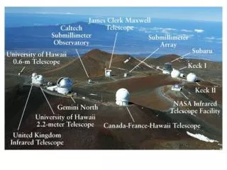
J-PARC (Japan Proton Accelerator Research Complex) Overview MLF (Material and Life Facility) Facility for material analysis and life science 400MeV Lineac 3GeV synchrotron Mercury target MLF
MLF spectrometers And more is being developed
MLF spectrometers Detectors are required to be… • Capable in high intensity • 100 * 100mm Size • < 1mm spatial resolution Detector Neutron beam (Various wave length) Θ Diffraction Target Mirror Diagrammatic sketch of Refelctrometer Neutron Reflectrometer A facility to analysis materials with reflection of neutrons
Diagrammatic sketch MSGC (Micro Strip Gas Counter) Electron Anode Avalanche Cathode • Micro-strip electrodes patterned on glass plate • <100µm between anode & cathode • Up to 1600V between each strips • Electron is multiplied with avalanche and produces charge • Charge division readout method for 1D position detection • 2D position detection by layering 2 plates
MSGC (Micro Strip Gas Counter) • High count rate • Low cost • Could be used with high pressure gas Good Anode Cathode • Charge up causes decrease of gas gain • Damage caused by sudden discharge • Bad in stability Bad
Grid2 Grid1 Small surface charge Low surface resistance Multi-grid-type MSGC (M-MSGC) • Charge up causes decrease of gas gain • Damage caused by sudden discharge • Bad in stability Bad Separation of two strong electric fields ... Anode Cathode Vanode > Vgrid1 > Vgrid2 > Vcathode Avoid charge-up and sudden discharge
A test plate consists of 4 grids + anode + cathode 400mm G1 G3 A G2 G4 C 4 cm x 4 cm active area Anode width: 5 µm 4 grids(20,25,35,42.5µm) and 10 µm gaps
Pulse Height Spectrum for 6keV X-rays 6keV Experiment is done with 6keV X-ray (@KEK Photon Factory) 0.1mmϕ beam, 400cps/mm2 Ar(30) + CH4(70%)@1atm Ar escape Obtained energy resolution was 14.6% FWHM. (Gas gain =3000)
Neutron Image by Floating Pad Charge Division Method 6mm 6mm 1mm Spatial resolution0.6mm FWHM
Active scintillator method (proposed in MILAND) Incident neutron MSGC Tcharge signal Electron drift d Position Measurement at T=Gap/Vdrift Primary light Tprimary light Photo Multiplier Primary light signal enables to calculate the depth of interaction information, and reduce parallax error
Problems of conventional method Incident neutron MSGC Stop Unwanted diffraction Incident neutron Primary light Photo Multiplier Since neutrons have to go through the MSGC, unwanted diffractions and stops can be caused. Position Measurement at T=Gap/Vdrift
Problems of conventional method Incident neutron Primary light Electron drift MSGC Photo Multiplier In order to avoid unwanted diffraction or stop, MSGC should be under the conversion area. However, since ordinary MSGC’s are not transparent, primary light cannot get to PMT.
Problems of conventional method Incident neutron Primary light Electron drift MSGC Photo Multiplier But if the MSGC is transparent…,
Problems of conventional method Incident neutron Primary light d Electron drift MSGC Photo Multiplier But if the MSGC is transparent…, primary light signal enables to calculate the depth of interaction information, and reduce parallax error without worrying about the unwanted diffraction
ITO MSGC • ITO(Indium Tin Oxide) is known as a transparent conductive material used for LCD display. • Optical transmission is 80-90%. • We fabricated a multi-grid-type MSGC using ITO. • OA10 glass substrate • 170nm thick ITO layer • Use with Ar/CF4 gas for efficient GSPC
This is ITO MSGC If you have super excellent eyes, may be you can see…
Picture of ITO MSGC ITO version of M-MSGC Electrode pattern is same as our conventional M-MSGC
Anode HV (4ch out put) ORTEC 710 55Fe 3mm 3.0cm PMT Hamamatsu R5600U Anode Cathode Grid 1 F 8.0mm Socket E5780 Tektronix DPO 4034 Oscilloscope Grid 2 Chamber inside Active area 2.7 cm PMT or ANODE - 800V ORTEC 570 Cathode HV(2ch out put) ORTEC 456 Pocket MCA 8000A PC Experimental Setup Ar(70%) + CH4(30%)@1atm Charge Signal Optical Signal PMTR5600U Sensitive Area 300nm~650nm
Test of operation as a proportional counter ANODE signal CATHODE signal Ar 70% + CH4 30%
100ns LIGHT CHARGE
ITO M-MSGC Obtained energy spectra Charge Light FWHM 25.4% FWHM 27.4%
Gas gain & PMT Spectra AMPLITUDE ANODE HV
HV (4ch out put) ORTEC 710 3mm Anode Hamamatsu R2486-02 PSPMT Cathode Tektronix DPO 4034 Oscilloscope Chamber inside PMT or ANODE - 1100V ORTEC 570 HV(2ch out put) ORTEC 456 MPA PC 6keV X-ray Test of position readout Experimental setup Ar(90%) + CF4(10%)@1atm Charge Signal Optical Signal PS PMT R-2486 Sensitive wave length 300nm~650nm Position Readout ORTEC 464
Position measurement Hamamatsu R2486-02 PSPMT PS Module Ar/CF4 90:10 X1 X2 Y1 Y2 ITO-MSGC ORTEC 464
5mm Position scanned result obtained with PSPMT 6keV collimated X-ray beam (scanned in 25mm * 25mm area) 5mm Experiment is done with 6keV X-ray (@KEK Photon Factory) 0.1mmϕ beam, 400cps/mm2 Hamamatsu PS-PMT R-2486-2 + Ortec 464 Position Detection module ≈2.5mm(FWHM) Count Channel
Results of position scan by 5mm 5mm 5mm Experiment is done with 6keV X-ray (@KEK Photon Factory) 0.1mmϕ beam, 400cps/mm2 Hamamatsu PS-PMT R-2486-2 + Ortec 464 Position Detection module Y Axis (Peak channel) X Axis (Peak channel)
Future work He3 + CF4 He3 + CF4 Transmissivity ITO-MSGC SiPM array Optical mask (position modulation) ITO-MSGC Charge signal (Y) Normal PMT Light signal (X) Use both of charge/optical signal for position detection
Future work He3 + CF4 ITO-MSGC Anger camera PMT
Summary • ITO M-MSGC has been fabricated and tested with 6keV X-rays. • Position sensing by optical signal has been demonstrated. • Active scintillation could be a solution for higher spatial resolution • Optics for better light collection should be considered.
Thank you Takeshi Fujiwara fujiwara@n.t.u-tokyo.ac.jp
A G C Pad Charge stay on pads Avalanche region Readout Strips 2D Multi-Grid-Type MSGC by induced charge sensing • Place FLOATING pads close to cathode • Positive Ions stay on pads • Pad charge can be read out through substrate