Download
1 / 56
560 likes | 618 Views
Learn about the major filter categories in frequency domain methods such as low-pass, high-pass, band-pass, and band-stop filters. Understand how each type of filter preserves or removes specific frequency components to enhance or suppress image details. Gain insights into complex multiplication techniques and steps involved in frequency domain filtering. Explore examples and practical considerations for applying filters in both spatial and frequency domains.

E N D
Frequency Domain Filtering CS474/674 - Prof. Bebis Sections 4.7, 4.8, 4.9, 4.10
Frequency Domain Methods Frequency Domain Spatial Domain
Major filter categories • Typically, filters are classified based on their properties in the frequency domain: (1) Low-pass (2) High-pass (3) Band-pass (4) Band-stop
Example Original signal Low-pass filtered High-pass filtered Band-pass filtered Band-stop filtered
frequency domain Low-pass filters(i.e., smoothing filters) • Preserve low frequencies - useful for removing details and noise suppression. Example:
frequency domain High-pass filters(i.e., sharpening filters) • Preserves high frequencies - useful for highlighting details. Example:
frequency domain Band-pass filters • Preserves frequencies within a certain band. Example:
Band-stop filters • Removes frequencies within a certain band. Band-stop Band-pass
Frequency Domain Methods complex multiplication using real and imaginary parts Case 1: H(u,v) is specified in the frequency domain. Case 2: h(x,y) is specified in the spatial domain.
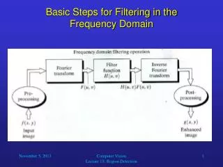
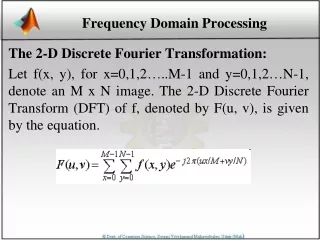
Frequency domain filtering: steps (note that P and Q must be powers of 2 to use FFT) F(u,v) = R(u,v) + jI(u,v)
Frequency domain filtering: steps (cont’d) (Case 1) complex multiplication G(u,v)= F(u,v)H(u,v) = H(u,v) R(u,v) + jH(u,v)I(u,v)
Example fp(x,y) f(x,y) fp(x,y)(-1)x+y F(u,v) G(u,v)=F(u,v)H(u,v) H(u,v) - centered g(x,y) gp(x,y)
(Case 2) h(x,y) specified in spatial domain • If h(x,y) is given in the spatial domain, H(u,v) can be generated as follows: • Form hp(x,y) by padding with zeroes. 2. Multiply by (-1)x+y to center its spectrum. 3. Compute its DFT to obtain H(u,v)
Example: h(x,y) is specified in the spatial domain 600 x 600 frequency spatial Sobel 602 x 602 frequency
Results of Filtering in the Spatial and Frequency Domains frequency domain filtering spatial domain filtering
Very Important: Preserving even/odd symmetrywhen padding with zeroes Sobel • Since h(x,y) is real and odd, H(u,v) should be imaginary and odd • We need to explicitly preserve odd symmetry of h(x,y) when padding with zeroes!
Important: Preserving even/odd symmetrywhen padding with zeroes (cont’d) Examples of 6 x 6 paddings: g(x,y)= -g(6-x,6-y) g(x,y) ≠ -g(6-x,6-y) 0 1 2 3 4 5 0 1 2 3 4 5 0 0 0 0 0 0 0 0 0 0 0 0 0 0 -1 0 1 0 0 0 -2 0 2 0 0 0 -1 0 1 0 0 0 0 0 0 0 0 0 0 0 0 0 0 0 0 0 0 0 0 -1 0 1 0 0 0 -2 0 2 0 0 0 -1 0 1 0 0 0 0 0 0 0 0 0 1 2 3 4 5 0 1 2 3 4 5 Sobel g(2,3)=-g(4,3) g(1,3) ≠ -g(5,3) (read details on pages 290-291 and 318-319)
Low Pass (LP) Filters • Ideal low-pass filter (ILPF) • Butterworth low-pass filter (BLPF) • Gaussian low-pass filter (GLPF)
Low-pass (LP) filtering • Preserves low frequencies, attenuates high frequencies. Ideal D0: cut-off frequency – user specified
Lowpass (LP) filtering (cont’d) • In 2D, the cutoff frequency is specified by the radius of a circle. Ideal
Choosing D0 • Most frequencies are concentrated around the center of the spectrum. • Consider a circle centered at point (N/2, N/2) in the frequency domain. • Choose the radius by specifying the percentage of total power to be preserved. e.g., preserve 80% of total power
Choosing D0 (cont’d) • Examples: r=8 (90% power) r=18 (93% power) original r: radius r=43 (95%) r=78 (99%) r=152 (99.5%)
Why LP perform smoothing? spatial domain freq. domain sinc * =
How does D0 control smoothing? (cont’d) • D0 controls the amount of blurring r=78 (99%) r=8 (90%)
Ringing Effect • Sharp cutoff frequencies produce an overshoot of image features whose frequency is close to the cutoff frequencies (ringing effect). h=f*g
Avoiding Ringing Effect • Attenuate higher frequencies smoothly. Ideal In practice D0: cut-off frequency – user specified
Butterworth LP filter (BLPF) n=1 n=4 n=16
Spatial Representation of BLPFs n=1 n=2 n=5 n=20
Comparison: Ideal LP and BLPF BLPF ILPF D0=10, 30, 60, 160, 460 D0=10, 30, 60, 160, 460 n=2
Gaussian: Frequency – Spatial Domains spatial domain frequency domain
Example 2: smoothing by GLPF D0=100 D0=80
High Pass (LP) Filters • Ideal high-pass filter (IHPF) • Butterworth high-pass filter (BHPF) • Gaussian high-pass filter (GHPF) • Difference of Gaussians • Unsharp Masking and High Boost filtering
High-pass filtering • Preserves high frequencies, attenuates low frequencies. H(u)
High-Pass filtering (cont’d) • A high-pass filter can be obtained from a low-pass filter: = 1 - D0
Butterworth high pass filter (BHPF) • In practice, we use filters that attenuate low frequencies smoothly (e.g., Butterworth HP filter) less ringing effect 1 -
Gaussian HP filter GHPF BHPF
Spatial Representation of High-pass Filters IHPF BHPF GHPF
Comparison: IHPF and BHPF IHPF D0=30,60,160 D0=30,60,160 n=2 BHPF
Comparison: BHPF and GHPF D0=30,60,160 BHPF n=2 D0=30,60,160 GHPF
Example: High-pass Filteringfor Fingerprint Image Enhancement BHPF (order 4 with a cutoff frequency 50)
Difference of Gaussians (DoG) filter Approximates the Laplacian This is a high-pass filter!
Highboost Filtering (revisited) Unsharp Masking: Highboost filtering: (previous formulation) Highboost filtering: (textbook’s formulation)
Highboost Filtering (revisited) FT Highboost Filter
Highboost and High-Frequency-Emphasis Filters 1+k k1+k2 1 k1 High-emphasis Highboost
Example GHPF D0=40 High-emphasis High-emphasis and hist. equal. High-Frequency Emphasis filtering Using Gaussian filter k1=0.5, k2=0.75
Homomorphic filtering • Can be used to remove shading effects in an image (i.e., due to uneven illumination) • Enhance high frequencies. • Attenuate low frequencies but preserve fine detail.
Homomorphic Filtering (cont’d) • Consider the following model of image formation: • Illumination i(x,y) varies slowly and affects low frequencies mostly. • Reflection r(x,y) varies faster and affects high frequencies mostly. i(x,y): illumination component r(x,y): reflection component
How are frequencies mixed together? • Low frequencies from i(x,y) and high frequencies from r(x,y) are convolved together. • When applying filtering, it is difficult to handle low/high frequencies separately.