Download
1 / 20
200 likes | 217 Views
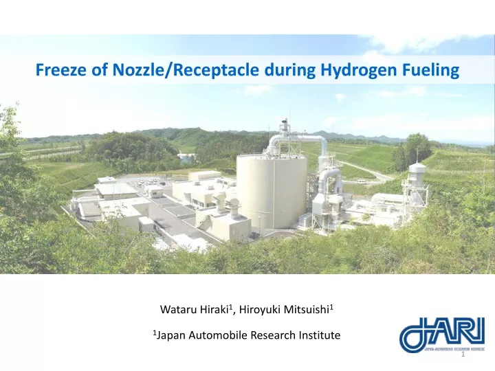
Freeze of Nozzle/Receptacle during Hydrogen Fueling. Wataru Hiraki 1 , Hiroyuki Mitsuishi 1 1 Japan Automobile Research Institute. Hydrogen station. http://hysut.or.jp/. Compressor. Pressure vessel. Dispenser. FCV. Overpressure. 87.5. Overfill. SOC 100%. 70. Pressure [MPa]. Overheat.

E N D
Freeze of Nozzle/Receptacle during Hydrogen Fueling Wataru Hiraki1,Hiroyuki Mitsuishi1 1Japan Automobile Research Institute
Hydrogen station http://hysut.or.jp/ Compressor Pressure vessel Dispenser FCV Overpressure 87.5 Overfill SOC 100% 70 Pressure [MPa] Overheat use Pre-cool 15 85 -40 Temperature [°C] Hydrogen station is possible about fast-fueling safely, using pre-cool
Issue of nozzle/receptacle freeze lock Receptacle Nozzle Disconnection Freeze lock Ice forms during fueling which causes the nozzle and receptacle to freeze together. This phenomenon is not specific to a single nozzle/receptacle design.
Object Safety evaluation of the nozzle/receptacle freeze lock Confirmation of a water amount to cause the freeze lock
Test condition & Experiment setup Fueling gas: Hydrogen, 35 MPa Gas temperature: -40°C Gas Sensor Ambient temperature: 30°C Hydrogen Ambient humidity: 95 %RH Flow rate: 650 g/min T Fueling time: 3 min Test interval: 10 min Thermocouple T T Nozzle: A, B(Two types) N2 T Water added : Nozzle, Receptacle Nozzle Receptacle Nitrogen Condition for the end of the test: Freeze lock occured or pass for 5 times Incubator
Experiment setup Receptacle Incubator Receptacle Nozzle connected nozzle
Disconnect procedure (1) Slidable locking sleeve is released (2) Draw out the nozzle ⇒disconnect Chuck Receptacle Receptacle Receptacle (1') Chuck goes up (※Shape of the sleeve and inner chuck are estimated) Chuck Procedure for identification of freeze lock Sleeve Sleeve Sleeve • Check immediately after the fueling • Action for the disconnection; • Revolve → Release the locking mechanism → Draw out • Identify as freeze lock if the nozzle is not disconnected in the above condition Nozzle Nozzle Nozzle Chuck
Water Spraying Position Receptacle Nozzle Hydrogen Gas Line Pin Cover spray Nozzle Receptacle Sleeve Chuck Fitting part Fitting part
Result Freeze lock is caused by water inside the nozzle. Hydrogen does not leak from the nozzle/receptacle even if the nozzle/receptacle were freeze lock. Freeze lock does not cause any damage of the equipment.
Estimation of freezing part Chuck Receptacle Clearance of sleeve Chuck part Fitting part Sleeve Nozzle Estimated freezing part:Clearance of sleeve, Chuck part
Effect of a water amount on freeze lock Water injection method Micropipette Nozzle head Water is injected to the nozzle inside before fueling. Connect to receptacle and flow -40°Cgas Freeze lock?
Test condition & Experiment setup Fueling gas: Hydrogen, 35 MPa Gas Sensor Gas temperature: -40°C Hydrogen Ambient temperature: 30°C Ambient humidity: 60 %RH Flow rate: 650 g/min Thermocouple Fueling time: 3 min T T N2 Nozzle: A Nozzle Receptacle Water added : injection the Nozzle Incubator Nitrogen
Result of Quantification After fueling Freeze lock
Conclusions ・ The nozzle and the receptacle are safely, even if the freeze lock occurred ・ The freeze lock is caused by the water freezing in the locking mechanism of the nozzle ・ The freeze lock occurred after fueling when water of 1000 μL over 750 μL injected to the nozzle A
Next step Experiment of the freeze lock Investigation of the freeze lock with other nozzles. Investigation of ambient condition when the freeze lock occurs. Investigation of a technique that protect the freeze lock. Proposition of the freeze lock testing condition and procedure
ACKNOWLEDGEMENTS This study is a summary of the “Hydrogen Using Technology Research and Development Project”, and the "Hydrogen production, transportation and storage system technology development" under consignment by the New Energy and Industrial Technology Development Organization (NEDO). Thank you for your attention