Download
1 / 10
100 likes | 329 Views
A Possible New RF FOIL for the VELO UPGRADE. Ray Mountain, Sheldon Stone Syracuse University. RF FOIL & RF BOX. CURRENT DESIGN. Separate modules from beam vacuum Foil is 300 um AlMg3, coated with insulator and getter Foil shape set by overlapping sensors and beam clearance

E N D
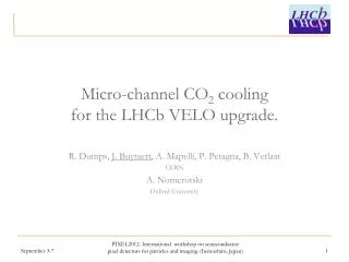
A Possible New RF FOIL for the VELO UPGRADE Ray Mountain, Sheldon Stone Syracuse University
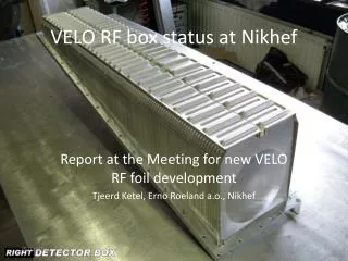
RF FOIL & RF BOX CURRENT DESIGN • Separate modules from beam vacuum • Foil is 300 um AlMg3, coated with insulator and getter • Foil shape set by overlapping sensors and beam clearance • Large area: 200 x 1000 mm2 • Maximum allowed pressure differential: 5 mbar (=> 10 kg = 22 lb) • Shield against beam-induced EMI • Wakefield suppressors to adapt beam pipe geometry • Was a huge engineering effort (NIKHEF) cross section ~1mm FOIL INSIDE VIEW OF RF-BOX MOUNTED IN VACUUM VESSEL R. Mountain, Syracuse University SU HEP Group Meeting, 1 Apr 2009 -2-
BEAM’S-EYE VIEW CURRENT DESIGN van Beuzekom – RD07 R. Mountain, Syracuse University SU HEP Group Meeting, 1 Apr 2009 -3-
RF FOIL REQUIREMENTS Physics: Must not allow excessive multiple scattering should have the smallest radiation length possible (e.g., low Z) in acceptance should minimize total material before first measured point [MFL,PC] Must allow detectors to overlap, for reasons of tracking (i.e., no acceptance gaps) and alignment will have complicated corrugated shape Must get as close as possible transversely to IP must allow approach to be < ~7.mm (original design goal was 5.mm, accelerator limit in 2001) Must stand high radiation environment without degradation in mechanical or electrical properties must withstand ~500 Mrad dose [MA] Mechanical: Separate primary vacuum <1e-9 mbar (accelerator) from secondary vacuum ~1e-4 mbar (detector), and maintain this ultra-high vacuum level must have no pinholes or virtual leaks outgassing must be minimal Must mechanically hold differential vacuum of ~5.mbar (transient) to ~1e-4 mbar (steady) without rupturing or even deflecting so as to touch sensors (1 mm clearance) must be strong (to this level of load) must be stiff must have low fatigue, for repeated pumpings must hold mechanical stability and accuracy (tolerances) Electrical: Must shield against RF EMI pick-up effects from accelerator (noise in detectors) must provide enough RF skin depth thickness (T<10-3) must be made at least partly of good conductor must reduce any surface/skin effects (?) [MFL] Must not electrically short sensors if contact is made must have inner insulating surface or coating Thermal: Must handle heating effects (electronics, beam wakefield) and cooling effects (modules, bb radiation) and not thermally deform so as to damage sensors must have sufficiently low CTE from about +40ºC down to -30ºC (? plus beam heating) wakefield power dissipation can be large (~kW) Perhaps like it to help with cooling the electronics [pref not req’d] low emissivity surface (or coating), or actual cooling of foil (active/passive) [SB] would need then to bleed off heat away from sensors Beam (Electrodynamic): Must suppress wakefield impact on beams need smooth geometry to reduce effects [MFL] need continuous electrical contact from one end to the other [MFL] should have a small beam aperture [PC] Must be “dynamic”-vacuum-compatible (i.e., effects due to presence of beam, which means ion-induced desorption, synchrotron radiation, electron multipacting) [MFL] so need NEG coating on UHV side plus ??? R. Mountain, Syracuse University SU HEP Group Meeting, 1 Apr 2009 -4-
IDEAS FOR UPGRADE DESIGN (1) Consider having NO RF shield Variation of BTEV idea of having sensors in primary vacuum, using wires or strips to guide the beam (mirror) current and local cryo-pumping to remove outgassing A major re-think would be needed, since no place for wires with overlaps and many opportunities to despoil primary vacuum (2) Use existing technology, make foil thinner by better fabrication method This is being pursued by NIKHEF, for the current AlMg3 alloy Also Totem (@LHC) idea of using 150 um Inconel (Ni-Cr) foil at a distance of 1 mm from beam (3) Use carbon fiber composite substrate and replication technology Like that used in RICH-1 mirrors (orig. BTEV RICH) (4) Some other (crazy) idea Adapt RF cloth Adapt RF laminates … R. Mountain, Syracuse University SU HEP Group Meeting, 1 Apr 2009 -5-
Composite Mirror Applications Inc. Initial conversations very promising They are interested in this project CMA has experience producing Spherical mirrors for LHCb RICH-1 Prototypes for BTEV RICH mirrors Many space-based mirrors and structures for NASA Manufacture technique Compression molding replication Make forms (positive + negative) Lay up sheets of CF “cloth” and “uni” with resin Apply elevated pressure and temperature to forms, resin flows, squeezes layup to required thickness Can replicate features down to 3 mm (or maybe smaller), as long as they are on the forming mandrel Have good control of thickness variations Have solved adhesion problem in vacuum 18 years experience in high strength Aluminum adhesion to polymers R. Mountain, Syracuse University SU HEP Group Meeting, 1 Apr 2009 -6-
FIRST ORDER DESIGN (1) Keep same design as current foil as a basis for discussions, for now Replace AlMg3 by CFRP composite plus Al deposition and NEG on accelerator side plus insulator deposition on VELO side (n.b. CF is conductive) Produce foil + box + flange as an integrated unit Avoids welding and other sealing problems No seams, better for vacuum tightness FOIL FLANGE BOX “straw man” R. Mountain, Syracuse University SU HEP Group Meeting, 1 Apr 2009 -7-
FIRST ORDER DESIGN (2) Material Use same material as RICH1 mirrors M46J Carbon fibers + EX-1515 resin Large modulus fibers Low density Resin has “high” radiation resistance and low outgassing Resin resists microcracking Layup: 4 ply thick ~ 0.4 mm Aluminum: 10 um thick (can do thicker but introduces complications) Radiation length R. Mountain, Syracuse University SU HEP Group Meeting, 1 Apr 2009 -8-
FIRST ORDER DESIGN (3) • RF shielding • Aluminum has skin depth 13 um @ 40 MHz (18 @ 20) • But CF is conductive, so can get reflection from it also • (will calculate when get conductivity info from CMA) • Mechanical stability under vacuum • Simple plate approximation • Min thickness required for 1 mm max deflection with load 10 mbar • AlMg3: 310 um (0.36%RL) • CFRP: 250 um (0.11%RL) (not too stupid: early FEA with real foil design showed 0.35 mm deflection for 0.25 mm thick Al under 15 mbar) • If stiffer can make inner radius smaller (maybe) R. Mountain, Syracuse University SU HEP Group Meeting, 1 Apr 2009 -9-
OUTLOOK Looks promising ! No obvious show-stoppers met (yet) PRACTICAL: Manufacturing Prototype foil (+ box) can proceed as soon as can provide CMA with a design They can handle some of the metrology and testing for this WORK YET TO DO: Mechanical / Thermal Need real deflection calculations (FEA, trying LISA) for mech, thermal effects Vacuum Can CF hold required vacuum at this thickness? May be a permeability issue Must test it to find out Need to bake out at some high temperature Beam Calculate wakefield effects (MAFIA) Acceptable heat dissipation in VELO Eventual measurements of shielding and power transfer Dynamic vacuum effects Radiation damage effects on CFRP R. Mountain, Syracuse University SU HEP Group Meeting, 1 Apr 2009 -10-