Download
1 / 20
210 likes | 430 Views
Betatron Resonance Compensation at the CERN PS Booster Synchrotron Ursch ütz Peter (EBG MedAustron). Outline. Brief information on the PS Booster Synchrotron Motivation for the betatron resonance compensation Measurement set-up, constraints and strategy Some measurement results

E N D
Betatron Resonance Compensation at the CERN PS Booster Synchrotron Urschütz Peter (EBG MedAustron)
Outline • Brief information on the PS Booster Synchrotron • Motivation for the betatron resonance compensation • Measurement set-up, constraints and strategy • Some measurement results • 3rd order resonance • Alternative working point for the PS Booster • Conclusions Urschütz Peter
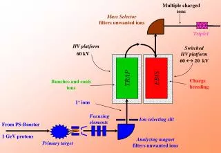
The PS Booster in the CERN accelerator chain The PS Booster (PSB) consists of 4 superimposed rings. • 40 years old machine • The PSB links the Linac 2 and the Proton Synchrotron (PS). • Direct beam supplier for the On-line Isotope Mass Separator facility (ISOLDE). Urschütz Peter
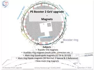
PS Booster Key data: • Radius: 25 m (1/4 of PS) • 16 identical periods • Lattice type: regular triplet (QF – QD – QF) • Cycle time: 1.2 s • Multi-turn injection (up to 13 turns) Protons: • Energy: at injection: 50 MeV at extraction: 1.4 GeV • Intensities: up to 1013 (in all 4 rings) The PS Booster ring Assembly of one period Urschütz Peter
Motivation for resonance compensation • Large incoherent space charge tune spread (for high intensity beams) – “Necktie” shaped area • Nominal tunes: Qx=4.17, Qy=5.23 • At injection: Tunes moved to: Qx=4.26, Qy=5.58 • Resonances to be considered: 2nd and 3rd order (e.g. 3Qy = 16) • PSB offers a variety of multipoles (only up to sextupoles used for resonance compensation). • Resonance compensation already done 35 years ago (orthogonal search for proper multipole currents) Betatron resonance compensation is mandatory for a satisfactory performance of the PSB! PSB tune diagram for high intensity beams. Urschütz Peter
How to measure and compensate resonances ? X1, X2 from BPMs (normalized amplitudes) Beam position Normalised phase space FFT Relation between spectral decomposition of particle motion and Hamiltonian perturbation theory (Normal Form) Driving terms: hjklm (strength and phase of the resonance) – prop. to multipole coefficients Fourier spectrum Urschütz Peter
Measurement system • 2 BPMs were used in the PSB. • 5 electrode signals were converted into sum and difference signals. • Digitiser (Acqiris modules): • 2 modules with each 4 channels • fsampl=500 MS/s (~800 samples/turn) • memory: 2MS/channel record ~2500 turns • Control and Processing Program • Controls the digitiser • Graphical user interface • Digital data conversion into beam position Urschütz Peter
Constraints in the PSB 1) Limitation to injection energy (50 MeV) PSB does not offer a dedicated kicker Injection mis-steering had to be used to obtain sufficiently large oscillation amplitudes. Resonance studies were limited to injection energy. 2) Decoherence of the BPM signals due to chromaticity • Only one sextupole family for chromaticity correction available. Decoherence of one signal in the transverse planes is unavoidable (natural chromaticities: Q’x~ -3.5, Q’y~ -9.3) • For purely horizontal or vertical resonances: no problem, chromaticity corrected in one plane. • Limitation if coupling resonances are considered, because both (horizontal and vertical) beam position signals are needed. Urschütz Peter
Measurement set-up What do we need to determine resonance driving terms? • A bunched beam performing coherent oscillations with a reasonably large oscillation amplitude (some mm) over a sufficiently large number of turns (some 100). A decoherence of the signal (chromaticity, amplitude detuning) should be avoided. Measurement set-up: • One third of the ring was filled to obtain a quasi-bunched beam (containing 1 to 2 * 1011 protons). • RF was already switched on at injection to avoid longitudinal debunching. • Use of injection mis-steering. • For each measurement only a single resonance was considered. • Tunes close to resonance condition, • Chromaticity adjusted either to zero in one plane or to reasonably low values in both planes (coupling resonances). Urschütz Peter
Procedure for determination of resonance driving terms • Measurements for the bare (uncorrected) machine; result: resonance vector • Reference measurements with a defined multipole excitation (for calibration purposes). • Simulation of the resonance phases for the compensation elements. • Calculation of compensation currents for multipoles • New measurements with compensation currents (if necessary second iteration was done). Reference measurements and simulation: (e.g.: Skew Sextupole(XSK2L4) = -45 A) - Opposite polarity of the skew sextupole magnet was indeed verified during the shut down period! - Measurement includes contribution from bare machine. Urschütz Peter
Measurement results:3Qy=16 resonance (skew sextupole resonance) • It’s a systematic resonance (16 periods in PSB)! • It has to be compensated in standard operation (with skew sextupoles). • Corresponding resonance driving term: h0030 • Resonance spectral line (in vertical spectrum): (0,-2) • Tunes: Qy ~ 5.35 (close to resonance condition: Qy =5.333) • Interest only in vertical particle motion. • Vertical chromaticity was corrected to zero. Urschütz Peter
3Qy=16 – uncorrected Phase and amplitude data obtained from Fourier spectra Beam intensity Vertical beam position Normalised phase space resonance strength and phase: Fourier spectrum Urschütz Peter
3Qy=16 – compensated Beam intensity Vertical beam position Normalised phase space Results from the measurements: |h0030| = 9.0±0.6*10-3 mm-1/2 ψ0030 = -21º±14º Calculated compensation currents (for two independent skew sextupoles): IXSK2L4 = -29.3 A, IXSK9L1 = +15.3 A Fourier spectrum Urschütz Peter
Further results… • Further resonances studied and compensated: • Quadrupole resonance: 2Qy = 11 • Linear coupling resonance: Qx - Qy = -1 • Other third order coupling resonances: 2Qx - Qy = 3, 2Qx + Qy = 14, Qx + 2Qy = 15 e.g.: 2Qy=11 – quadrupole resonance uncorrected corrected Urschütz Peter
Further studies… • Studies with different injection mis-steering (oscillation amplitudes) • Studies with different chromaticities • By chance we got clear signs of a decapole resonance: • 5Qy = 27 Fivefold symmetrie due to decapole resonance 5Qy = 27 Urschütz Peter
Alternative working point • Qx= 4.17, Qy= 4.23 instead of Qx= 4.17, Qy= 5.23 (Qy is shifted one integer down) • Main motivation: To avoid the systematic 3rd order 3Qy=16 resonance. 2Qy=11 vs. 2Qy=9 3Qy=16 vs. 3Qy=13 PSB tune diagram for standard working point. PSB tune diagram for alternative working point. Urschütz Peter
Alternative working point • Relevant resonances show clearly smaller intrinsic excitation • Comparison of results for 3Qy=16 vs. 3Qy=13 Resonance strength |h0030|: 9.0 * 10-3 mm-1/2 2.2 * 10-3 mm-1/2 • bare machine component is a factor 4 less for lower working point Urschütz Peter
Alternative working point Crossing of 3Qy = 13 in rings 1 and 2. ring 2 …uncorrected ring1 …compensated ring 2 No compensation is needed for ring 2! ring1 Urschütz Peter
Conclusions • All second and third order resonances relevant for operation were analyzed for rings 1 and 2 of the PS Booster. • The acquisition system used allowed fast and efficient determination of resonance driving terms on the basis of turn-by-turn beam position measurements. • All relevant resonances were successfully compensated • Comparative resonance driving term measurements for two different working points; conclusion is that from a resonance excitation point of view, a “lower” working point is preferable. • PS Booster is still operated with the lower working point. Urschütz Peter
Thank you for your attention! Urschütz Peter