Download
1 / 44
440 likes | 890 Views
Normal Stress (1.1-1.5). MAE 314 – Solid Mechanics Yun Jing. Pretest.

E N D
Normal Stress (1.1-1.5) MAE 314 – Solid Mechanics Yun Jing Normal Stress
Pretest This is a structure which was designed to support a 30kN load, it consists of a boom AB and of a rod BC. The boom and rod are connected by a pin at B and are supported by pins and brackets at A and C. (1) Is there a reaction moment at A? why? (2) What is the reaction force in the vertical direction at A? (3) What is the internal force in AB? (4) What is the internal force in BC?
Statics Review Pins = no rxn moment Normal Stress
Solve for reactions at A & C: Statics Review • Ay and Cy can not be determined from these equations. Normal Stress
Consider a free-body diagram for the boom: substitute into the structure equilibrium equation • Results: Statics Review Bx See section 1.2 in text for complete static analysis and review of method of joints. Normal Stress
Introduction to Normal Stress • Methods of statics allow us to determine forces and moments in a structure, but how do we determine if a load can be safely supported? • Factors: material, size, etc. • Need a new concept….Stress Normal Stress
Introduction to Normal Stress Stress = Force per unit area Normal Stress
Introduction to Normal Stress • If stress varies over a cross-section, the resultant of the internal forces for an axially loaded member is normal to a section cut perpendicular to the axis. Thus, we can write the stress at a point as • We assume the force F is evenly distributedover the cross-section of the bar. In realityF = resultant force over the end of the bar. Normal Stress
Introduction to Normal Stress Sign conventionTensile (member is in tension) Compressive (member is in compression) Units (force/area) English: lb/in2 = psi kip/in2 = ksi SI: N/m2 = Pa (Pascal) kN/m2 = kPa MPa, GPa, etc. Tensile Compressive Normal Stress
A F’ F Definitions and Assumptions • Homogenous: material is the same throughout the bar • Cross-section: section perpendicular to longitudinal axis of bar • Prismatic: cross-section does not change along axis of bar Prismatic Non-Prismatic Normal Stress
Definitions and Assumptions • Uniaxial bar: a bar with only one axis • Normal Stress (σ): stress acting perpendicular to the cross-section. • Deformation of the bar is uniform throughout. (Uniform Stress State) • Stress is measured far from the point of application. • Loads must act through the centroid of the cross-section. Normal Stress
“Uniform” Stress Definitions and Assumptions • The uniform stress state does not apply near the ends of the bar. • Assume the distribution of normal stresses in an axially loadedmember is uniform, except in theimmediate vicinity of the points ofapplication of the loads (Saint-Venant’s Principle). Normal Stress
Definitions and Assumptions • How do we know all loads must act through the centroid of the cross-section? • Let us represent P, the resultant force, by a uniform stress over the cross-section (so that they are statically equivalent). Normal Stress
Definitions and Assumptions • Moments due to σ: • Set Mx = Mx and My = My Equations for the centroid Normal Stress
Example Problem • Can the structure we used for our statics review safely support a30 kN load? (Assume the entire structure is made of steel with a maximum allowable stress σall=165 MPa.) Cross-section 30 mm x 50 mm Normal Stress
Example Problem • Two cylindrical rods are welded together and loaded as shown. Find the normal stress at the midsection of each rod. Normal Stress
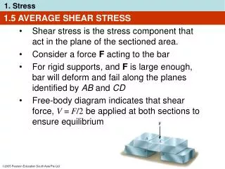
Shearing and Bearing Stress (1.6-1.8, 1.12) MAE 314 – Solid Mechanics Yun Jing Shearing and Bearing Stress
What is Shearing Stress? • We learned about normal stress (σ), which acts perpendicular to the cross-section. • Shear stress (τ) acts tangential to the surface of a material element. Normal stress results in a volume change. Shear stress results in a shape change. Shearing and Bearing Stress
Where Do Shearing Stresses Occur? • Shearing stresses are commonly found in bolts, pins, and rivets. Bolt is in “single” shear Free Body Diagram of Bolt Force P results in shearing stress Force F results in bearing stress (will discuss later) Shearing and Bearing Stress
Shear Stress Defined • We do not assume τ is uniform over the cross-section, because this is not the case. • τ is the average shear stress. • The maximum value of τ may be considerably greater than τave, which is important for design purposes. Shearing and Bearing Stress
Double Shear Bolt is in “double” shear Free Body Diagram of Bolt Free Body Diagram of Center of Bolt Shearing and Bearing Stress
Bearing Stress • Bearing stress is a normal stress, not a shearing stress. • Thus, where Ab = projected area where bearing pressure is applied P = bearing force Single shear case Read section 1.8 in text for a detailed stress analysis of a structure. Shearing and Bearing Stress
Would like to determine the stresses in the members and connections of the structure shown. From a statics analysis: FAB= 40 kN (compression) FBC = 50 kN (tension) Must consider maximum normal stresses in AB and BC, and the shearing stress and bearing stress at each pinned connection
At the flattened rod ends, the smallest cross-sectional area occurs at the pin centerline, Rod & Boom Normal Stresses The rod is in tension with an axial force of 50 kN. At the rod center, the average normal stress in the circular cross-section (A = 314x10-6m2) is sBC = +159 MPa. The boom is in compression with an axial force of 40 kN and average normal stress of –26.7 MPa. The minimum area sections at the boom ends are unstressed since the boom is in compression.
The cross-sectional area for pins at A, B, and C, The force on the pin at C is equal to the force exerted by the rod BC, The pin at A is in double shear with a total force equal to the force exerted by the boom AB, Pin Shearing Stresses
Divide the pin at B into sections to determine the section with the largest shear force, Evaluate the corresponding average shearing stress, Pin Shearing Stresses
To determine the bearing stress at A in the boom AB, we have t = 30 mm and d = 25 mm, To determine the bearing stress at A in the bracket, we have t = 2(25 mm) = 50 mm and d = 25 mm, Pin Bearing Stresses
Equilibrium of Shear Stresses • Consider an infinitesimal element of material. Apply a single shear stress, τ1. • Total shear force on surface is (τ1)bc. • For equilibrium in the y-direction, applyτ1 on (-) surface. • For moment equilibrium about the z-axis,apply τ2 on top and bottom surfaces. • Moment equilibrium equation about z-axis: • Thus, a shear stress must be balanced by three other stresses for the element to be in equilibrium. t2 t1 t1 t2 Shearing and Bearing Stress
Equilibrium of Shear Stresses • What does this tell us? • Shear stresses on opposite (parallel) faces of an element are equal in magnitude and opposite in direction. • Shear stress on adjacent (perpendicular) faces of an element are equal in magnitude and both point towards or away from each other. • Sign convention for shear stresses • Positive face – normal is in (+) x, y, or z direction • Negative face - normal is in (-) x, y, or z direction + t2 t1 t1 + - t2 - Shearing and Bearing Stress
Define General State of Stress y • σx = stress in x-direction applied in the plane normal to x-axis • σy = stress in y-direction applied in the plane normal to y-axis • σz = stress in z-direction applied in the plane normal to z-axis • τxy = stress in y-direction applied in the plane normal to x-axis • τxz = stress in z-direction applied in the plane normal to x-axis • τzy = stress in y-direction applied in the plane normal to z-axis • And so on… z x Shearing and Bearing Stress
Define General State of Stress y • There are 9 components of stress: σx, σy, σz, τxy, τxz, τyx, τyz, τzx, τzy • As shown previously, in order to maintain equilibrium: τxy= τyx, τxz = τzx, τyz = τzy • There are only 6 independent stress components. z x Shearing and Bearing Stress
Example Problem • A load P = 10 kips is applied to a rod supported as shown by a plate with a 0.6 in. diameter hole. Determine the shear stress in the rod and the plate. Shearing and Bearing Stress
Example Problem • Link AB is used to support the end of a horizontal beam. If link AB is subject to a 10 kips compressive force determine the normal and bearing stress in the link and the shear stress in each of the pins. Shearing and Bearing Stress
Oblique Planes and Design Considerations (1.11, 1.13) MAE 314 – Solid Mechanics Yun Jing Oblique Planes and Design Considerations
Stress on an Oblique Plane • What have we learned so far? • Axial forces in a two-force member cause normal stresses. • Transverse forces exerted on bolts and pins cause shearing stresses. Oblique Planes and Design Considerations
Stress on an Oblique Plane • Axial forces cause both normal and shearing stresses on planes which are not perpendicular to the axis. • Consider an inclined section of a uniaxial bar. • The resultant force in the axial directionmust equal P to satisfy equilibrium. • The force can be resolved into components perpendicular to the section, F, and parallel to the section, V. • The area of the section is Oblique Planes and Design Considerations
Stress on an Oblique Plane • We can formulate the average normal stress on the section as • The average shear stress on the section is • Thus, a normalforce applied to a bar on an inclined section produces a combination of shear and normal stresses. Oblique Planes and Design Considerations
Stress on an Oblique Plane • Since σ and τ are functions of sine and cosine, we know the maximum and minimum values will occur at θ = 00, 450, and 900. At θ=±900σ=0 At θ=±450σ=P/2A0 At θ=00 σ=P/A0 (max) At θ=±900τ=0 At θ=±450τ=P/2A0 (max) At θ=00 τ=0 Oblique Planes and Design Considerations
Stress on an Oblique Plane • What does this mean in reality? Oblique Planes and Design Considerations
Design Considerations • From a design perspective, it is important to know the largest load which a material can hold before failing. • This load is called the ultimate load, Pu. • Ultimate normal stress is denoted as σu and ultimate shear stress is denoted as τu. Oblique Planes and Design Considerations
Design Considerations • Often the allowable load is considerably smaller than the ultimate load. • It is a common design practice to use factor of safety. Oblique Planes and Design Considerations
Example Problem • Two wooden members are spliced as shown. If the maximum allowable tensile stress in the splice is 75 psi, determine the largest load that can be safely supported and the shearing stress in the splice. Oblique Planes and Design Considerations
Example Problem • A load is supported by a steel pin inserted into a hanging wooden piece. Given the information below, determine the load P if an overall factor of safety of 3.2 is desired. Oblique Planes and Design Considerations