Download
1 / 35
350 likes | 471 Views
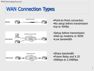
Chapter 13: Frame Relay & ATM. Business Data Communications, 6e. WAN Alternatives. WAN Alternatives. Integrated Network Access Using Dedicated Channels. Integrated Network Access Using Public Switched WAN. X.25 Key Features .

E N D
Chapter 13:Frame Relay & ATM Business Data Communications, 6e
X.25 Key Features • Call control packets carried on the same channel and same virtual circuit as data packets. • Multiplexing of virtual circuits takes place at layer 3. • Both layer 2 & 3 include flow and error control mechanisms
Frame Relay Key Features • Designed to be more efficient than packet switching • Designed to eliminate excessive X.25 overhead • Call control signalingis on a separate logical connection from user data. • Multiplexing and switching of logical connections takes place at layer 2. • No hop-by-hop flow control and error control.
Frame Relay Characteristics • Control signaling takes place on a separate logical connection (nodes don’t need state tables for each call) • Multiplexing/switching take place at layer 2, eliminating a layer of processing • No hop-by-hop flow/error control
Frame Relay vs. X.25 • Reliability • Frame relay loses ability to do link-by-link flow and error control. • X.25 link level protocol provides reliable hop-by-hop link control • With increasing reliability of transmission and switching facilities, this is not a major disadvantage. • Streamlining • Frame relay reduces need for protocol functionality at the user-network interface, and reduces internal network processing • Improvement in throughput using frame relay, compared to X.25, of an order of magnitude or more
Frame Relay Control Plane • Similar to common channel signaling, in that a separate logical channel is used for control information. • At the data link layer, LAPD (Q.921) provides a reliable data link control service, with error control and flow control, between user (TE) and network (NT). • This data link service is used for the exchange of Q.933 control signaling messages.
Frame Relay User Plane • User-plane protocol is LAPF (Link Access Procedure for Frame Mode Bearer Services), defined in Q.922 • Core functions of LAPF are used for frame relay: • Frame delimiting, alignment, and transparency • Frame multiplexing/demultiplexing using address field • Inspection of frame contents • Inspection of the frame to ensure that it is neither too long nor too short • Detection of transmission errors • Congestion control functions
User Data Transfer • No control field; connection mgt must be carried out on a separate channel, and there is no flow or error control • Flag and frame check sequence (FCS) fields function as in HDLC. • Information field carries higher-layer data • Address field length determined by the address field extension (EA) bits
Frame Relay Call Control • Establish a logical connection between two endpoints, and assign a unique DLCI to the connection • Exchange information in data frames. Each frame includes a DLCI field to identify the connection • Release the logical connection
Frame Relay Congestion Control • Two strategies supported in frame relay • Congestion avoidance procedures are used at the onset of congestion to minimize the effect on the network • Congestion recovery procedures are used to prevent network collapse in the face of severe congestion
Congestion Notification Bits • Backward Explicit Congestion Notification (BECN): Indicates that the frame that the user transmits on this logical connection may encounter congested resources. • Forward Explicit Congestion Notification (FECN): Indicates that the frame has encountered congested resources.
Asynchronous Transfer Mode (ATM) • Also known as cell relay • Faster than X.25, more streamlined than frame relay • Supports data rates several orders of magnitude greater than frame relay • Data on logical connection is organized into fixed-size packets, called cells. • No link-by-link error control or flow control.
Virtual Channels & Virtual Paths • Logical connections in ATM are virtual channels • analogous to a virtual circuit in X.25 or a frame relay logical connection • used for connections between two end users, user-network exchange (control signaling), and network-network exchange (network management and routing) • Variable rate, full duplex flow is exchanged • A virtual path is a bundle of virtual channels that have the same endpoints.
Advantages of Virtual Paths • Simplified network architecture • Increased network performance and reliability • Reduced processing and short connection setup time • Enhanced network services
Virtual-Path/Virtual-Channel Characteristics • Quality of service • Switched and semi-permanent virtual-channel connections • Cell sequence integrity • Traffic parameter negotiation and usage monitoring
ATM Control Signaling:Virtual Paths • Semipermanent virtual channels may be used for user-to-user exchange; no control signaling is required. • Meta-signaling channel, a permanent low-data-rate channel used for a virtual channel that can be used for call control • user-to-network signaling virtual channel can than be used to set up virtual channels to carry user data • can also be used to set up a user-to-user signaling virtual channel within a preestablished virtual path
ATM Control Signaling:Virtual Paths • A virtual path can be established on a semipermanent basis by prior agreement. No control signaling is required. • Establishment/release may be customer controlled. Customer uses a signaling virtual channel to request the virtual path from the network. • Establishment/release may be network controlled. Network establishes a virtual path (may be network-to-network, user-to-network, or user-to-user)
ATM Cell Fields • Generic Flow Control (GFC) is used for control of cell flow only at the local user-network interface, to alleviate short-term overload conditions in the network. • Virtual Path Identifier (VPI) field constitutes a routing field for the network. • Virtual Channel Identifier (VCI) field is used for routing to and from the end user. • Payload Type (PT) field indicates the type of information in the information field. • Cell loss priority (CLP) bit is used to provide guidance to the network in the event of congestion. • Header Error Control (HEC) field is used to correct and detect errors in the header
ATM Service Categories • Real-Time Service • Constant bit rate (CBR) • Real-time variable bit rate (rt-VBR) • Non-Real-Time Service • Non-real-time variable bit rate (nrt-VBR) • Available bit rate (ABR) • Unspecified bit rate (UBR) • Guaranteed frame rate (GFR)
Real Time Service • Constant Bit Rate (CBR)- simplest service to define- used by applications that require a fixed, continuously available data rate- commonly used for uncompressed audio and video
Real Time Service • Real-Time Variable Bit Rate (rt-VBR)- intended for time sensitive applications- transmits at a rate that varies with time- can be bursty
Non-Real Time Services • Non-Real Time Variable Bit Rate (nrt-VBR)-end system specifies a peak cell rate, sustainable cell rate and how bursty the cells may be- network allocates resources to provide low delay and minimal cell loss
Non-Real Time Services • Unspecified Bit Rate (UBR)-suitable for TCP based traffic -cells are forwarded on a FIFO basis-delays and variable losses are possible-used for text/image/data transfer, messaging, distribution, retrieval and remote terminal
Non-Real Time Services • Available Bit Rate (ABR)-specifies a peak and minimum cell rate -network resources are allocated to at least the minimum level-used for LAN interconnections
Non-Real Time Services • Guaranteed Frame Rate (GFR)-designed to support IP backbone subnetworks.-seeks to optimize frame-based traffic from a LAN through a router onto an ATM backbone