Download
1 / 31
310 likes | 469 Views
Long-Term SINR Calibration for System Simulation. Date: 2014-01-20. Authors:. Simulation Scenario. PHY statistics ( Freq-domain SINR distribution). MAC calibration. Overview. Static Radio statistics ( S/I distribution). PHY Tput calibration .

E N D
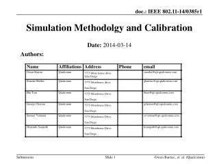
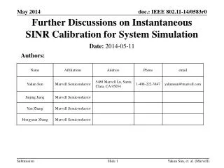
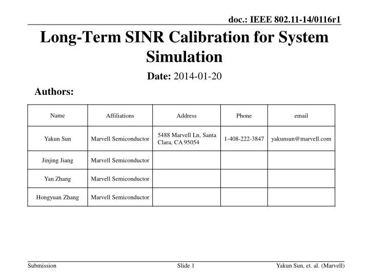
Long-Term SINR Calibration for System Simulation Date: 2014-01-20 Authors: Yakun Sun, et. al. (Marvell)
Simulation Scenario • PHY statistics • (Freq-domainSINRdistribution) • MAC calibration Overview • Static Radio statistics • (S/Idistribution) • PHY Tput calibration • A step-by-step calibration was proposed in [1] with high level descriptions. • More details and examples of the first step of statistics-based calibration in this contribution. • Results also provide some insights of the simulation scenario under development. Yakun Sun, et. al. (Marvell)
Static Radio Characteristics: Long Term SINR • Geometry, or long-term SINR, defines the average quality of reception. • Expected received (desired) signal power over the sum of the interference power (and noise). • Expected received signal power of (desired or interfering) transmitter • Include large scale fading (path-loss, shadowing factor) • Include static transmission/receiving factors (transmit power, antenna gain, cable loss, noise figure, etc) • Does not include small scale fading. • Propose to use long-term SINR as a static radio characteristic for system simulator calibration. • Long-term SINR provide a high-level picture of the network (deployment and basic transmitter/receiver/propagation configuration). • Calibrating long-term SINR aligns the system modeling. • Long-term SINR is easy to calibrate. Yakun Sun, et. al. (Marvell)
Definition of Long-Term SINR in WiFi • Contention based channel access in WiFi leads to no strict definition of long term SINR. • Some rough definition is used. • A good definition should capture the deployment and long term radio statistics. • Example: DL SINR of STA-m associated with AP-n Yakun Sun, et. al. (Marvell)
Discussions on Long-Term SINR • DL/UL traffic time ratio models • Assume αDL+ αUL=1 a fully occupied network • Case 1: αDL: αUL =1 equal traffic in both way • Case 2: αDL : αUL =1:NSTA equal traffic from each STA including AP. • Probability of collision roughly models CSMA • CSMA off All transmitters will transmit anyway, and will creates interference at receiver. • CSMA on A transmitter (TX2) will listen before transmit, and will not create interference to RX if it can hear TX1 is talking. Yakun Sun, et. al. (Marvell)
Tested Long-Term SINR • 4 types of long-term SINR are tested in our contribution. Yakun Sun, et. al. (Marvell)
Uplink Long-Term SINR • Similarly, uplink long-term SINR can be defined as: • Average UL SINR per AP • UL SINR per AP-STA link • An example of uplink long-term SINR under equal STA/AP traffic with CSMA off Yakun Sun, et. al. (Marvell)
Procedure of Statistics Collection • The definition (and the parameters, such as αUL/αDL and PCCA if apply) is selected and fixed before calibration. • For the selected calibration scenario, multiple drops of STA/AP is done for convergence. • In each drop: • Drop STAs/APs, and associate each STA with an AP. • Randomly drop or load prefixed locations. • Fixed association or signal-strength based association • After STA/AP are dropped and associated, collect the long-term SINR observed at each STA (downlink) and AP (uplink). • After multiple drops: • Generate the distribution (CDF) of long-term SINR for STAs (downlink) and APs (uplink) respectively collected over multiple drops. Yakun Sun, et. al. (Marvell)
Simulation Setup • Simulation is based on scenario 1 to 4 in [2]. • Distribution of downlink long-term SINR are plotted as an example. • Detailed/optional simulation assumptions: • 2.4GHz Channel with 20MHz Bandwidth • Noise Figure: 7dB • Thermal noise: -174dBm/Hz • No antenna gain, no cable loss • Expected received signal power is defined in Appendix. • CCA threshold: -82dBm • Randomly drop STAs and APs (if apply) • Association based on scenarios (fixed for scenario 1-2, signal-strength based for scenario 3-4). • Detailed simulation assumptions (which is not defined yet in [2]) in Appendix. Yakun Sun, et. al. (Marvell)
Simulation Assumptions (Scenario 1) Yakun Sun, et. al. (Marvell)
Scenario 1 – Residential: SINR AP-AP, AP-STA and STA-STA: channel B 10 STA per BSS • Scenario 1 is a severe interfered case (CSMA reduces interference by more than 20dB). Yakun Sun, et. al. (Marvell)
Simulation Assumptions (Scenario 2) Based on [2] before the document was updated at the meeting. Yakun Sun, et. al. (Marvell)
Scenario 2 – Enterprise: SINR • Scenario 2 is a sever interfered case (CSMA reduces interference by about 20dB). • DL/UL traffic impact SINR more with CSMA due to the limited number of strong interfering APs. Yakun Sun, et. al. (Marvell)
Simulation Assumptions (Scenario 3) Yakun Sun, et. al. (Marvell)
Scenario 3 – Indoor Small BSSs: Received SINR • Scenario is a severe interfered case (CSMA reduces interference substantially). • DL/UL traffic impact SINR more without CSMA due to the large number of strong interfering APs. Yakun Sun, et. al. (Marvell)
Simulation Assumptions (Scenario 4) Yakun Sun, et. al. (Marvell)
Scenario 4 – Outdoor Large BSSs: Received SINR • Scenario is a severe interfered case (CSMA reduces interference substantially). • Using the same channel type for STA-STA causes a long tail for DL/UL=1/N (more severe interfering STAs) Yakun Sun, et. al. (Marvell)
Observations • All types of long-term SINR give very good insights into the system modeling and captures fundamental characteristics for calibration. • Long-term SINR distributions with different traffic model (UL/DL time ratio) are within a relatively small difference. • Long-term SINR distributions with or without CSMA are with some dBs shift. • We can select a type of definition solely based on complexity of calibration. • Least ambiguity with equal STA/AP traffic and without CSMA. Yakun Sun, et. al. (Marvell)
Summary • Use the distribution of long term SINR as the metric for system simulator calibration. • For simplicity and avoiding ambiguity, use the definition with equal STA/AP traffic and without CSMA as the metric for calibration. Yakun Sun, et. al. (Marvell)
References [1] 11-13-1392-00-0hew-methodology-of-calibrating-system-simulation-results [2] 11-13-1001-05-0hew-HEW-evaluation-simulation-scenarios-document-template Yakun Sun, et. al. (Marvell)
Appendix: Expected Received Signal Power • Received signal power at receiver RX from transmitter TX. Yakun Sun, et. al. (Marvell)
Appendix: Scenario 1 – Residential: Received Signal Power Yakun Sun, et. al. (Marvell)
Appendix: Scenario 1 – Residential: Interference Signal Power Yakun Sun, et. al. (Marvell)
Appendix: Scenario 2 – Enterprise: Received Signal Power Yakun Sun, et. al. (Marvell)
Appendix: Scenario 2 – Enterprise: Interference Signal Power Yakun Sun, et. al. (Marvell)
Appendix: Scenario 3 – Indoor Small BSSs: Received Signal Power Yakun Sun, et. al. (Marvell)
Appendix: Scenario 3 – Indoor Small BSSs: Received Signal over white noise Yakun Sun, et. al. (Marvell)
Appendix: Scenario 3 – Indoor Small BSSs: Interference Signal Power Yakun Sun, et. al. (Marvell)
Appendix: Scenario 4 – Outdoor Large BSSs: Received Signal Power Yakun Sun, et. al. (Marvell)
Appendix: Scenario 4 – Outdoor Large BSSs: Received Signal over white noise Yakun Sun, et. al. (Marvell)
Appendix: Scenario 4 – Outdoor Large BSSs: Interference Signal Power Yakun Sun, et. al. (Marvell)