Download
1 / 1
30 likes | 311 Views
Development of a Depth Gage Instrument for Orthopedic Surgery Brian Cost 1 , Justin Johnson 1 , Tyler Kibbee 1 Advisor: Derek Lewis 2 , Director of Engineering Vanderbilt University Engineering School , Biomedical Engineering Department OrthoHelix Surgical Designs, Inc. BACKGROUND.

E N D
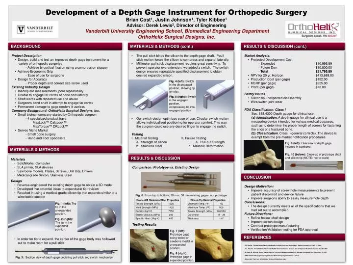
Development of a Depth Gage Instrument for Orthopedic Surgery Brian Cost1, Justin Johnson1, Tyler Kibbee1 Advisor: Derek Lewis2, Director of Engineering Vanderbilt University Engineering School, Biomedical Engineering Department OrthoHelix Surgical Designs, Inc. BACKGROUND MATERIALS & METHODS (cont.) RESULTS & DISCUSSION (cont.) • Project Description • Design, build and test an improved depth gage instrument for a variety of orthopedic surgeries • - Achieve bi-cortical fixation using a compression stopper • Achieve Ergonomic Grip • - Ease of use for surgeons • Design for Accuracy • - Proper depth and correct size screw used • Existing Industry Design • Inadequate measurements, poor repeatability • Unable to engage far cortex of bone consistently • Shaft warps with repeated use and abuse • Surgeons bend shaft in attempt to engage far cortex • Permanent damage to gage renders it useless • Company Background: OrthoHelix Surgical Designs, Inc. • Small biotech company started by Orthopedic surgeon • - 4 specialized product trays • MaxLock™ CalcLock™ • MaxTorque™ DRLock™ • Serves Niche Market • - Small bone surgery • - Hand and Foot specialists • The pull stick binds the silicon to the depth gage shaft. Ppull stick motion forces the silicon to compress and expand laterally. • Millimeter pull stick displacement requires great sensitivity. To prevent operator overextension, we added a switch. The switch design ensures repeatable specified displacement to obtain desired expanded silicon. • Our switch design optimizes ease of use. Circular switch motion allows individualized positioning for operator comfort. This way, the surgeon could use any desired finger to engage the switch. • Testing • I. Material Testing II. Failure Testing • a. Strength of silicon a. Pull-out Strength • b. Stainless steel b. Material Deformation • Market Analysis: • Projected Development Cost: • - Expended $10,995.89 • - Future Dev. $10,800.00 • - Total $21,795.89 • NPV for 20 yr. Horizon $413,689.00 • Production Cost (per gage) $152.00 • MSRP (per gage) $225.00 • Profit (per gage) $73.00 • Safety Issues • Silicon tip unexpected disassembly • Wire/switch joint wear • FDA Classification: Class I • Sec. 888.4300 Depth gauge for clinical use. • (a) Identification. A depth gauge for clinical use is a measuring device intended for various medical purposes, such as to determine the proper length of screws for fastening the ends of a fractured bone. • (b) Classification. Class I (general controls). The device is exempt from the pre-market notification procedures Fig. 4 (left): Switch in the disengaged position, allowing tip to relax. Fig. 5 (right): Switch in the engaged position, compressing tip into engaged position Fig. 9 (left): Overview of depth gage inserted in sawbone. Fig. 10 (below): Close-up of prototype shaft and silicon tip (NOTE: not to scale) MATERIALS & METHODS • Materials • SolidWorks, Computer • SLA printer, SLA devices • Saw bone models, Plates, Screws, Drill Bits, Drivers • Medical-grade Silicon, Stainless Steel Design • Reverse-engineered the existing depth gage to obtain a 3D model • Developed five potential ideas to expandable tip revision • Resulted in using a medical-grade silicon tip that expands similar to a wine bottle stopper • In order for tip to expand, the center of the gage body was hollowed out to make room for a pull stick RESULTS & DISCUSSION Comparison: Prototype vs. Existing Design Testing Results CONCLUSION • Design Motivation: • Improve accuracy of screw hole measurements to prevent patient discomfort and device failure • Improve surgeons ability to easily measure hole depth • Conclusions: • The design currently meets all of the specifications that we had set out to accomplish. • Future Directions: • Refine hollow shaft design • Improve switch design • Contract prototype manufacturing • Verification/Validation testing for FDA approval Fig. 6: From top to bottom; 30 mm, 50 mm existing gages, our prototype Fig. 1 (left): The tip in the unexpanded position. Fig. 2 (right): The tip in the expanded position. Fig. 7 (left): Prototype gage being tested on sawbone model in unexpanded position. Fig. 8 (right): Prototype gage in expanded position. REFERENCES R.D. Guyer. "United States Patent # 5,928,243: Pedicle probe and depth gage". Spinal Concepts Inc. July 27, 1999. D.A. Fischer. "United States Patent # 4,450,834: External fixation device". Ace Orthopedic Manufacturing Inc. May 29, 1984. M. Dace, B. Wilfong. United States Patent # 7,293,364: Measurement device". Warsaw Orthopedic, Inc. November 13, 2007 MSC Industrial Supply Company Website, Material Property Information. Silicon Azom.com The A to Z of Materials. Grade 420 Stainless Steel Fig. 3: Section view of depth gage depicting pull stick and switch mechanism.