Download
1 / 103
1.98k likes | 3.63k Views
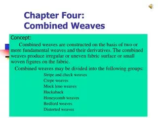
Chapter 9 Combined Stresses. 9-1 Introduction. Basic types of loading: axial, torsional and flexural Stress formulas: Axial loading - Torsional loading - Flexural loading -. 9-2 Combined Axial & Flexural Loads.

E N D
9-1 Introduction • Basic types of loading: axial, torsional and flexural • Stress formulas: Axial loading - Torsional loading - Flexural loading -
For stiff members the formula is appropriate For long slender members or columns, the effect of P-d is significant
Hw10 sallow B D2 D1 Fig. P-908 ค่า z1-z6 ได้จากเลขประจำตัวนิสิต ดังต่อไปนี้ 46z1z2z3z4z5z6 D1=(1+z1) in. D2 = D1(1+z2) in. I1-1=1000(1+z3) in4 Area=10(1+z4) in2 B =10(1+z5) in. sallow=10(1+z6) ksi. หมายเหตุD2= D1(1+z2) in. เพื่อให้หน้าตัดมีประสิทธิภาพดีในการรับหน่วยแรง
Hw11 L4 L2 L3 b h L1 ค่า z1-z6 ได้จากเลขประจำตัวนิสิต ดังต่อไปนี้ 46z1z2z3z4z5z6 L1= (1+z1) in. L2 = (1+z2) in. L3= (1+z3) in. L4 = (1+z4) in. b = 0.2(1+z5) in. h = b(1+z6) in. P =(1+z5) kips. F =(1+z6) kips. หมายเหตุh = b(1+z6) in. เพื่อให้คานมีความลึกไม่น้อยกว่าความกว้างเสมอ
The maximum eccentricity to avoid tension The general case: The position of neutral axis (line of zero stress) That is in designing of masonry or other structures weak in tension, the resultant load should fall in the middle third of the section.
918 A compressive load P= 12 kips is applied, as in Fig. 9-8a, at a point 1 in. to the right and 2 in. above the centroid of a rectangular section for which h=10 in. and b=6 in. Compute the stress at each corner and the location of the neutral axis. Illustrate the answers with a sketch similar to Fig. 9-8b.
921 Calcualte and sketch the kern of a W360 X 122 section.
9-5 Stress at A Point Stress at a point really defines the uniform stress distributed over a differential area.
The most general state of stress at a point may be represented by 6 components, symmetry state of stress เมื่อแสดงด้วยระบบโคออร์ดิเนต (xyz) symmetry state of stressเมื่อแสดงด้วยระบบโคออร์ดิเนต (xyz)
Plane Stress - state of stress in which two faces of the cubic element are free of stress. For the illustrated example, the state of stress is defined by • State of plane stress occurs in a thin plate subjected to forces acting in the midplane of the plate. • State of plane stress also occurs on the free surface of a structural element or machine component, i.e., at any point of the surface not subjected to an external force.
Plane Stress Two methods to compute the maximum stresses i.e., • Analytical approach • Using of Mohr’s circle
Find maximum or minimum s differentiating Eq.(9-5) w.r.t. q and setting the derivative equal to zero Find maximum or minimum t differentiating Eq.(9-6) w.r.t. q and setting the derivative equal to zero Eq.(9-5) Eq.(9-6)
At zero shearing stress t = 0 Eq.(9-5) Eq.(9-6) ซึ่งเป็นมุมเดียวกับสมการ Eq.(9-7)ดังนั้น ค่า maximum or minimumsจะเกิดขึ้นเมื่อ t = 0
มุมqและ qs ต่างกัน 45O Maximum or minimum t Maximum or minimum s (Principal stresses)
9-7 Variation of Stress at A Point: Mohr’s Circle Otto Mohr (1882) Eq.(9-5) Eq.(9-6) Eq.(a)2 + Eq.(b)2
x-axis y-axis Rule for Applying Mohr Circle to Combined Stresses
x-axis C y-axis
x-axis n-axis R 2q q C y-axis
x-axis n-axis R 2q q C y-axis
R 2q1 x-axis C y-axis 2q2
y-axis R C 2q1 x-axis
y-axis R 60o C x-axis 45o
s2 s1 s2 s1 s1 s2 9-8 Absolute Maximum Shearing Stress Mohr’s circle: Rotation around z-axis