Download
1 / 21
210 likes | 232 Views
Learn about HIAPER Data Acquisition System for atmospheric research applications. Discover the system architecture, data flow, processing methods, and hardware requirements.

E N D
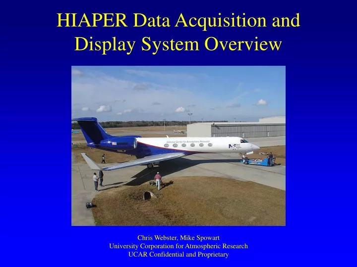
HIAPER Data Acquisition and Display System Overview Chris Webster, Mike Spowart University Corporation for Atmospheric Research UCAR Confidential and Proprietary
Other Systems (2003) • University of Wyoming • Single computer 6U VME • NOAA • P3 uses vacuum tubes, GIV has RAF system • Working on a new data system • CIRPAS • Distributed National Instruments with Labview display • SATCOM • NASA DC-8 • small system for internal use only
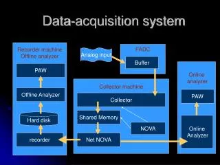
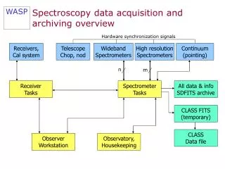
System Architecture; Data Flow Onboard Data Server Transmit UDP to ground sql database DSM Data Logger UDP Broadcast DSM Onboard Display(s) Processor (time-series & 2d) Raw Data Inputs - Analog - Digital - Serial Onboard Display(s) SQL Database Real-time updates Historical data Data Acquisition and Recording Data Processing and Display
HIAPER Data Acquisition System Introduction • Minimize weight, size, and power. • Flexible, large number of standard interfaces, limited custom interfaces. • Suitable to G-V external operating environment. • Capable of operating unattended during flight, including take-off and landing. • Remote access to data system and network connected instruments provided by satellite communications.
Overview • Small distributed sampling modules (DSM). • Industry standard PC104 DSM architecture (ISA bus). • COTS hardware for digital interfaces. • Custom over sampling Sigma/Delta A/D converter with digital FIR filters. • Eventually replace ADS II in NCAR C-130 and NRL P3 aircraft (ADS III?).
Description • DSMs connected to host computer via local area network. • Host computer includes redundant CPUs, internal disks, power supplies, and dual external removable disk data recorders. • Raw data recorded in binary format backward compatible with present ADS-II. • Seven card PC-104 enclosure. Includes one slot for power supply, one for CPU, and one for timing card. • Up to 4 instrument interface cards in one DSM. • 5 ½ x 5 ½ x L.
Requirements • Digital data collection: • Serial data: • 11 channels asynchronous RS-232, RS-422, RS-485 up to 115K baud. • USB 1.1 host control, 2 channels for PMS-2D, ~ 200K bytes/sec. • ARINC-429 12.5K and 100K baud, 4 Rx, 2 Tx. • Programmable logic provided for ease of implementing bi-phase, APN-232, etc. Anything I/O card. • Parallel data: • Flexible 32-bit bi-directional bus with strobes. Configurable as 1x, 4x, 8x, 16x, and 32 bits. Anything I/O card. • Pulse counters: • 16-bits, double buffered with strobes. Anything I/O card.
Requirements Contd. • Computation: • Host PC control computer running Linux. • DSM processor running RTLinux. • Host control computer records data, runs instrument control program, interfaces to satcom, and runs data processing and local display programs. • Communications and Control: • 100baseT CAT-6 Ethernet data LAN (expandable to 1 GHz). • GUI soft-key programmable instrument control program via host control computer.
Requirements Contd. • Time Synchronization and Distribution: • GPS time-of-day distributed to DSMs via IRIG-B network from the time server. • GPS 1PPS signal distributed to all DSMs. • GPS time-of-day distributed via NTP. • Display: • Data recording, processing and display programs to run on host PC.
Hardware • Arcom Viper CPU (PDA): • Intel XScale 400 MHz processor. • 1.4W max. power dissipation. • -40° C to +85° C operating temp. range option. • 64M bytes RAM. • 256K bytes battery backed SRAM. • 10/100baseT Ethernet. • Dual USB ports (DSM console?). • 5 serial ports >= 230.4K baud(4 RS-232, 1 RS-422/485). • Jxi2, inc., IRIG-B time/frequency processor: • Multiple time code formats (IRIG-A, IRIG-B, DC Level Shift, etc.). • Three user selectable pulse outputs, 1 Hz – 1.5 MHz. • One “heartbeat” bus interrupt. • GPS 1 PPS input synchronization with internal clock, 10 MHz oscillator. • Power Supply: • +5, +/- 12 VDC PC-104 card AC-to-DC converter.
Network topology data-net Iridium-net display-net Inmarsat SATCOM DataServer DSM Display DSM TimeServer IRIG & NTP Display DSM DSM self-recordinginstrument
System Architecture; Data Flow Onboard Data Server Transmit UDP to ground sql database DSM Data Logger UDP Broadcast DSM Onboard Display(s) Processor (time-series & 2d) Raw Data Inputs - Analog - Digital - Serial Onboard Display(s) SQL Database Real-time updates Historical data Data Acquisition and Recording Data Processing and Display
Display System Architecture Onboard Server Raw Data Image Data Onboard Display(s) Processor (e.g. MCR) UDP Processor (time-series & 2d) UDP Broadcast Imaging (e.g. AIMR) netCDF (HRT) SQL (LRT) “Smart” Instruments SATCOM (on ground) QC Display(s) Video titling
Access to Data - onboard • ASCII data feeds of scalar time-series • Network UDP broadcast • Multiple and configurable • Serial feed; Digi SP-One (converts UDP to RS232) • SQL Database/repository • Network read-writable by anyone • has permissions control • easy to use and very common
Display Program • Portable (Windows, Linux & Mac) with ease of total install. Qt for GUI, Qwt for plotting. • As near real-time as possible (current delay is ~2.5 seconds from DAQ to display). • “standard” displays should cover all obvious and current time-series plots and RAF facility instruments. • Real-time & Post-processing
“Standard” display types • Time-series • XY & flight track • ASCII • lists • Fixed • QC • Histograms • PMS-2D • Skew-T • Imager which can handle “scans” as defined • Video (ftp direct to camera for RT). • GIF/PNG/JPG viewer
Quality Control/Check (QC) • Range check • Spike detection • Flat-line detection • Level shift
Display Hardware • Commodity rack mount (vs. built in) • Take advantage of latest technology • Laptop still best solution • Battery = UPS • Thin & light • Wireless notepad computers?