Download
1 / 71
740 likes | 1.06k Views
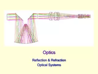
Optics. ISAT 241 Analytical Methods III Fall 2003 David J. Lawrence. Light as a Wave. Wave º motion (propagation) of a disturbance. Waves transport energy. Mechanical waves sound, earthquakes, and ocean waves require a “medium” that can be disturbed.

E N D
Optics ISAT 241 Analytical Methods III Fall 2003 David J. Lawrence
Light as a Wave • Waveºmotion (propagation) of a disturbance. • Waves transport energy. • Mechanical waves • sound, earthquakes, and ocean waves • require a “medium” that can be disturbed. • Light and radio waves are examples of “Electromagnetic waves”. • Disturbance is variations in electric (E) and magnetic (B) fields. • Since E and B can exist in a vacuum, electromagnetic waves do not require a medium.
= f ´ l v For light and other “Electromagnetic Waves”, in a vacuum: v = c = 2.9979 ´ 108 m/s In air: vair= 2.9970 ´ 108 m/s In glass: ~ vglass= 2.0 ´ 108 m/s 1 nanosecond = 1 ns = 1 x 10⁻⁹ s = one billionth of a second In 1 ns, light travels a distance of: ~ d = (3 ´ 108 m/s) (1 ´ 10-9 s) = 0.3 m = 1 ft For a “Harmonic Wave” (sinusoidal wave) Wave speed = frequency x wavelength
Medium Speed of Light Wavelength of Light (m/s) (nm) vacuum* 2.9979 x 10⁸º c589 air 2.9970 x 10⁸ 589 water 2.25 x 10⁸ 442 glass (crown) 1.97 x 10⁸ 387 diamond 1.24 x 10⁸ 243 Speed and Wavelength of Light in Several Media (for light of frequency = 5.09 x 10¹⁴ Hz) ‘Yellow’ v = f ´l * Light travels at its maximum speed in a vacuum
f (Hz) l(nm) Color red 630-760 4.5 x 10¹⁴ orange 590-630 4.9 x 10¹⁴ yellow 560-590 5.2 x 10¹⁴ green 500-560 5.7 x 10¹⁴ blue 450-500 6.3 x 10¹⁴ violet 380-450 7.1 x 10¹⁴ These are average values!! For the visible portion of the spectrum, the wavelength in vacuum (or in air) ranges from: l = 400 nm to l = 700 nm l = 4000 Å to l = 7000 Å
Rays Wavefronts Light as a Wave A “plane wave” propagating to the right.
Rays Wavefronts A plane wave propagating to the right. The Ray Approximation “Rays” are straight lines perpendicular to the wavefronts. They point in the direction of motion of the wave.
Serway & Jewett, Principles of Physics Figure 25.1
Serway & Jewett, Principles of Physics Figure 25.2
Serway & Jewett, Principles of Physics Figure 25.3
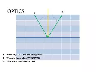
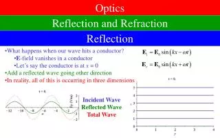
“Reflected Ray” “Incident Ray” “normal” q1 q1 q1 = q1 • Specular Reflection = Reflection from a Smooth Surface Law of Reflection The incident ray, the reflected ray, and the normal, all lie in the same plane Angle of reflection = Angle of incidence
Serway & Jewett, Principles of Physics Figure 25.5
v1 Field v2 Consider MRDs marching from a football field into a swamp . . . Swamp
c speed of light in a vacuum n º = v speed of light in the medium Wavelength of Light (nm) Index of Refraction, n Speed of Light Medium (m/s) vacuum 2.9979 x 10⁸ 589 1 air 2.9970 x 10⁸ 589 1.000293 water 2.25 x 10⁸ 442 1.333 glass (crown) 1.97 x 10⁸ 387 1.52 diamond 1.24 x 10⁸ 243 2.419 n > 1 The Index of Refraction, n , of a medium is defined as the ratio: n is dimensionless These values apply for light of frequency = 5.09 x 10¹⁴ Hz (‘Yellow’)
wavefronts Air = #1 Glass = #2 rays speed in vacuum wavelength in vacuum What happens when light travels from one medium into another? • The frequency does not change • The speed and wavelength do change • E.g. , when light goes from air into glass
Serway & Jewett, Principles of Physics Figure 25.11
v1 v2 What if columns of MRD’s enter the swamp at an angle? Field Swamp
“normal” “Incident Ray” “Reflected Ray” n1 Air n2 Glass “Refracted Ray” n1 sin q1= n2 sin q2 q2< q1 n2 >n1 Refraction of Light All rays and the normal lie in the same plane. The “Refracted Ray” is bent towards the normal. Law of Refraction - Snell’s Law
Serway & Jewett, Principles of Physics Figure 25.8
n1 sin q1= n2 sin q2 q2> q1 n2 <n1 Refraction of Light “Incident Ray” “Reflected Ray” “normal” Glass Air “Refracted Ray” All rays and the normal lie in the same plane. The “Refracted Ray” is bent away from the normal. Law of Refraction - Snell’s Law
Dispersion Therefore: • n depends on wavelength. • Light of different wavelengths will be refracted or bent at different angles when it enters a material. “Normal” “White light” The speed of light in any material depends on the frequency (or wavelength, or color) of the light. The material is said to exhibit “Dispersion”
air n2 = 1.00 q2=90° 0 % n1 = 1.50 glass q1=qc 100 % the “critical angle” Total Internal Reflection Snell’s Law : n1 sin q1 = n2 sin q2 For n1 > n2 , when q1= qc , q2 =90°, and Snell’s Law gives n1 sin qc= n2 sin 90°= n2
air n2 = 1.00 q2=90° 0 % n1 = 1.50 glass q1=qc 100 % the “critical angle” Total Internal Reflection
n2 1 qc = sin-1( ) = sin-1( ) qc = 41.8° n1 1.50 Total Internal Reflection (cont.) Total internal reflection occurs only when light attempts to go from a medium of higher index of refraction to a medium of lower index of refraction. For this example, when light attempts to go from glass with n1 = 1.50 into air with n2 = 1, For q1 > qc , the beam is entirely reflected at the boundary.
n2 Cladding Light Ray n1 Core Cladding typically q< 8 ° qc end view n1 n2 Fiber Optics
Light must fall inside this angle to be guided in the fiber core. n2 2 × Acceptance Angle 2 qaccept qc n1 Core n2 Acceptance Angle , qaccept Cladding air nair = 1 qaccept = sin-1 [ n12 - n22 ] Numerical Aperture = NA = sin qaccept = n12 - n22 Fiber Optics (cont.)
Pin Pout [ ] light power exiting the fiber a = -10 log10 light power coupled into the fiber [ ] [ ] Pout Pin a = -10 log10 = 10 log10 Pin Pout Not all of the light that gets into one end of an optical fiber gets out the other end. Total Fiber Transmission Loss (dB) = Total Fiber Attenuation (dB) = What if the length of the fiber is l ?
[ ] a [ ] Pout Pin 10 10 log10 log10 = = l l Pin l Pout fiber length in km Fiber Loss per Unit Length (dB/km) = Fiber Attenuation per Unit Length (dB/km) Total Fiber Loss (dB) = Fiber Loss per Unit Length (dB/km) ×l (km) • Accounts for transmission loss in the fiber, • NOT the losses encountered in getting the light into or out of the fiber (coupling losses).
[ ] power coupled into the fiber = -10 log10 power produced by the source [ ] power produced by the source = 10 log10 power coupled into the fiber Coupling Loss (in decibels) Not all of the source light output gets into the fiber. Coupling Loss (dB) = acoupling
Interference of Light Waves • “Superposition” • In order for us to be able to observe sustained interference between two or more light waves - • (1) The sources of the waves must be “monochromatic”, which means that they must have a single wavelength (or a single frequency, or a single “color”). • (2) The sources of the waves must be “coherent”, which means that the phase difference between the waveforms must remain constant, e.g.,
Huygens’ Principle All points on a given wave front are taken as point sources for the production of spherical secondary waves, called wavelets, which propagate outward with speeds characteristic of waves in that medium. After some time has elapsed, the new position of the wave front is the surface tangent to the wavelets. Page 1119 of the text
Interference of Waves Huygen’s Principle p. 1119 of the text
Source d viewing screen two slits in metal plate Young’s Double-Slit Experiment • Light exiting the two slits interferes. • In Phase Þ Constructive Interference