Download
1 / 15
150 likes | 392 Views
Improved Adjacent Channel Rejection Parameters to solve the Near-Far Interference Problem. Steve Brunson & Bob Soranno The Johns Hopkins University – Applied Physics Lab. Scenario of Interest.

E N D
Improved Adjacent Channel Rejection Parameters to solve the Near-Far Interference Problem Steve Brunson & Bob Soranno The Johns Hopkins University – Applied Physics Lab Steve Brunson & Bob Soranno (JHU/APL)
Scenario of Interest • Victim – A vehicle is parked in a gas station located on the corner of a major street. A large transaction is being performed on a short range link to an antenna under the canopy (~6m). (“Minimum” link power assumed) • Interference – The roadway is 15 meters from the parked vehicle. Vehicles on the road may be conducting Traffic Probe transactions at 20 dBm and Vehicle-Vehicle transactions at 33 dBm in other channels. Steve Brunson & Bob Soranno (JHU/APL)
The Near/Far Problem • Near – Loud transmitter on a different channel (interference) • “Far” – Distant or weak transmitter in tuned channel (desired signal) • Interferer “Keep Out” Range Desired– 15 m • Interference Power • Most transmitters will be 33 dBm or less Steve Brunson & Bob Soranno (JHU/APL)
Mitigation Approaches • Antenna Patterns –some help, but unfavorable geometries cannot be avoided • Added IF filtering (SAW) – can be effective (40 dB beyond adjacent channel), but will increase cost (~$10?). Could be required for interference outside the DSRC band. • Increased baseband filtering – effective, basis for Type 2 receiver • Increased desired signal level – effective for short, low power links (-21 to -4 dBm required for 6 meter link with 0/0 dBi antennas) Steve Brunson & Bob Soranno (JHU/APL)
Measure of Effectiveness • Interferer “Keep-Out” Range – How close can you let an out-of-channel interferer get before you start losing packets? • Inputs: • Level of Desired Signal (relative to MDS) • Level of Interference Rejection • Interference Power Transmitted • Antenna Patterns (0 dBi omni’s assumed) • Propagation (free space assumed) • Interference independent of own xmt pwr. Steve Brunson & Bob Soranno (JHU/APL)
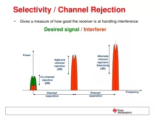
Limiting Conditions • Adjacent or Alternate Adjacent Channel Interference – leakage from strong signals in nearby channels • Front End Saturation – nonlinear effects caused by strong signals in any other channel or out-of-band signals • In general, Adjacent Channel problems seem more severe than Front End Saturation Steve Brunson & Bob Soranno (JHU/APL)
Keep-Out Range Plots • Keep-Out Range vs Received Power • Received Power from MDS to MDS + 20 dB • One line for each data rate with applicable MDS and ACI-rejection (per Atheros) • Blue Lines: Interference Power = 20 dBm • Green Lines: Interference Power = 33 dBm • Both antennas 0 dBi • 15 meter line in RED • Faster Modes Lower because of poorer MDS • [mds: -85 -84 -82 -80 -77 -70 -69 -67 dBm] Steve Brunson & Bob Soranno (JHU/APL)
Keep-Out Range: Type 2, Adj Chnl Steve Brunson & Bob Soranno (JHU/APL)
Keep-Out Range: Type 1, Adj Chnl Steve Brunson & Bob Soranno (JHU/APL)
Keep-Out Range: Type 1, Alt Adj Chnl Steve Brunson & Bob Soranno (JHU/APL)
Conclusions • Type 1 receivers will experience losses with 20 & 33 dBm adjacent channel interferers, BUT early deployment densities will be low. • Type 2 receivers will be OK except for high power interferers (40 & 44.8 dBm), but these should be low density and/or transitory. • Antenna Patterns will help the situation in most cases, especially high EIRP transmitters (these have narrow regions of max EIRP). Steve Brunson & Bob Soranno (JHU/APL)
Back-up Slides Steve Brunson & Bob Soranno (JHU/APL)
Keep-Out Range: Type 2, Alt Adj Chnl Steve Brunson & Bob Soranno (JHU/APL)
Front End Saturation • Saturation analysis based on information provided by Atheros • Saturation can be caused by signals outside the DSRC band • If out of band signals are a problem, a SAW filter in the IF may be required Steve Brunson & Bob Soranno (JHU/APL)
Saturation vs. ACI Max Gain – 10 dB Max Gain Steve Brunson & Bob Soranno (JHU/APL)