Download
1 / 51
590 likes | 1.13k Views
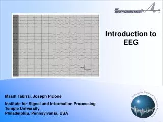
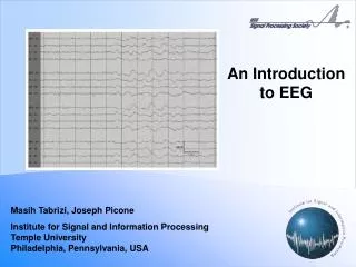
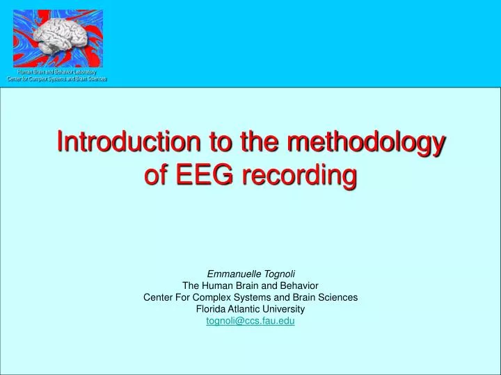
Introduction to the methodology of EEG recording. Emmanuelle Tognoli The Human Brain and Behavior Center For Complex Systems and Brain Sciences Florida Atlantic University tognoli@ccs.fau.edu. Summary . A. Generators and modulators of EEG signal B. Understanding instrumentation

E N D
Introduction to the methodology of EEG recording Emmanuelle Tognoli The Human Brain and Behavior Center For Complex Systems and Brain Sciences Florida Atlantic University tognoli@ccs.fau.edu
Summary • A. Generators and modulators of EEG signal • B. Understanding instrumentation • C. Main ethical issues • D. Physiological and electronical sources of noise • E. Constraints for experimental protocols in EEG • F. Configuration of EEG recording system and selection of montage • G. Management of connectics • H. Paste-up and problem solving during the recording session • I. Digitization • J. Cleaning/decontamination of sensitive equipment / equipment maintenance
Generators of EEG signal • When reached by an input, the presynaptic neuron: • Releases some neurotransmitter in the synaptic cleft • The dendritic process of the post-synaptic neuron: • shows a local change in its membrane’s permeability • generates a primary (intracellular) current from the locus of the synapse to the soma • Generates a secondary/return extracellular current to close the loop
Generators of EEG signal • Cortical pyramidal neurons, arranged in layers • The movement of the ions is creating an open field (no cancellation) • When a local community of tens of thousands of neurons are activated simultaneously by some input, a signal can be detected as far as at the surface of the scalp • This signal is EXTREMELY tiny, and requires many precautions when measured
Generators of EEG signal • And the miracle occurs
Modulators • Age • Children: • Changes in frequency content due to the size of the loops in the anatomical networks • Changes in the conduction time due to myelinization • Change in the amplitude of the signal due to myelinization • Adult • Increased variability over 40 • Vigilance • Chronopsychology (more details next) • Drugs • Caffeine • Body temperature • Hormonal cycles (women) • Laterality
Modulators • Circadian rhythms • Global power is maximal during the afternoon • Theta power has two peaks at 4pm and midnight • Induced alpha is maximal in the afternoon • Beta is maximal between 5pm and 7pm • The modulation is dependent on the location of the electrodes
Overview • Junction skin-electrode • Analog conduction • Differential amplifiers • ADC • Integration of triggers • Transfer to the CPU / storage
Transduction • The living tissues contain free ions • The wire is conveying electrons • The transfer of the signal from one material to the other requires a chemical transformation • Oxidation or reduction (AC)
e- e- Transduction • Eg. Ag / AgCl electrode: • OXIDATION • If an electron moves from the wire to the electrode toward the conductive gel: • It reacts with AgCl • e- + AgCl -> Ag + Cl- • Cl- becomes hydrated and enters the conductive paste • REDUCTION • If ion moves from the conductive gel to the electrode: • It reacts with solid Ag • Ag + Cl- -> e-+ AgCl • AgCl becomes insoluble • one electron is liberated to the wire • REVERSIBLE
Transduction • Eg. Ag / AgCl electrode: • The Ag/AgCl electrode is non-polarizable (or minimally polarizable) • POLARIZATION • The anion (Cation) is unable to move freely across the gel/electrode border • The concentration of ions at the border is altered. • Ions concentrate over the border with the electrode and create a steady potential (bi-layer, capacitance) • This steady potential hampers the movement of the charges • This is important since the biopotential we intend to measure is in the range of 1/1000 of the half-cell potential (local potential at the junction between the conductive paste and the electrode)
Analog conduction • As soon as the potentials are digital, they are immune to noise (not to deletion) • Between the cap and the ADC, the minuscule currents are traveling through the cables and in the amplifier. • Contamination through movements of the cables • Contamination by cross-talk inside the amplifier and at the multiplexer of the ADC
Differential amplification • We amplified to push the deflection of the pens (mechanical) • We amplify to bring the signal in the range of the ADC (usually 0-1 to 0-5 V)
Differential amplification • Principle of differential amplification: the CMR • (Signal + noise) – (noise) • Take a scalp electrode (say F3) and a fixed point (GND) • Measure one potential difference • Take a reference electrode (say M1) and a fixed point • Measure a second potential difference • (Signal + noise) – (noise) = “a very clean” signal
Differential amplification • The ability of the amplifier to reject the common mode noise is called the CMRR
Differential amplification • Amplifier Input impedance • Separate the differential input with a high resistance
Analog-to-Digital Conversion • Sampling frequency: Nyquist and aliasing
Analog-to-Digital Conversion • Sampling frequency • ADC range • Quantization
Acquisition and storage • Data acquisition and storage • Reasonable sampling rate • Backup
Understanding instrumentation • Quikcap • Headbox • Power unit • System unit
Electrical safety • Security for the subject and security for the equipment • Faulty connections • Additional devices (response pads, sensors) • Ground loops • Static discharges • Chassis leakage • EMI in crossing wires • Isolation amplifiers (Neuroscan system) are regulated by IEC 601-1 specifications. • Additional devices connected to Neuroscan have to be detailed in the application to the EEG committee • Order to plug or unplug the components
Infection risk • Most of the supplies, especially those in contact with the subject (eg. needles), are disposable • Any supply in contact with the subject does not return to the main. • eg. the gel is sampled in a cup. Do NEVER refill a syringe in the main container. • Moderate skin preparation: a subject should never be bleeding as a result of skin preparation. • Inspection for the presence of blood after experiment (to choose the decontamination procedure) • Decontamination of non-disposable equipment • Is regulated by [American Electroencephalographic Society. Report of the Committee on Infectious Diseases. J Clin Neurophysiol 1994;11:128-132.].
Infection risk Spaulding's classification of devices/medical instruments
Interferences • Physiological artifact • Ocular domain • Muscular domain • EKG • Respiratory • Movement • EDR/sweating • Subjects’ instruction and online monitoring • Instrumental noise • EMI : wireless or line noise (60 Hz) • Sway of the cable • Electrodes poorly attached (pop) • Electrode noise • Amplifier noise • Flicker noise (DC recordings!) • Amplifier blocking • Shielding and guarding
Interferences • Artifacts from the ocular domain
1 s Interferences • With proper alignment of EOG electrodes, horizontal EOG do not pick up the signal from vertical eye movements GOOD BAD
1 s Interferences • Saccade / eye movements
Interferences • Muscles
Interferences • How life could be easy without muscles
Interferences • (and with enough time to average thousands)
Interferences • EKG
Interferences • Respiratory
Interferences • Movement
Interferences • EDR/sweating
Interferences • Physiological artifact • Ocular domain • Muscular domain • EKG • Respiratory • Movement • EDR/sweating • Subjects’ instruction and online monitoring • Instrumental noise • Flicker noise (DC recordings!) • EMI : wireless or line noise • electrode noise • amplifier noise • Sway of the cable • Electrodes poorly attached (pop) • Amplifier blocking • Shielding and guarding
Interferences • A cell phone
Interferences • Poor contact / Electrode pop
Interferences • 60 Hz
Protocols • Paradigms • Evoked response • Steady-state paradigms • A single source of variation between conditions “All other things being equal” • A good Stimulation/recording coupling “time accuracy in analog and digital stimuli/triggers” • Subject screening • Day-before instruction • Accepting or rejecting a volunteer • artifacts instruction, task instructions, • Online monitoring of data quality and management of breaks
F. Configuration of EEG recording system and selection of montage
Configuration • Configuration of data recorder (scan-acquire mode) • Sampling frequency • DC/AC recording (DC and EDR resident on the skin; DC and choice of electrodes) • Triggers • Selection of montage • Only referential recording • Reference electrodes • Ground electrode • Ancillary recording (EOG, surface EMG, EKG)
Montage reference • Choice of the reference electrode • Cephalic/non cephalic • Well-attached • Single electrode or pair of electrode • Pair physically or digitally linked • Position of the ground • In midline for ERL • Remontage