Download
1 / 34
340 likes | 430 Views
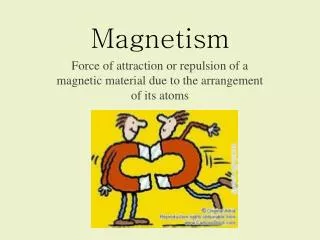
Magnetism. Auto 2 after series circuits. Magnets & Magnetic Fields. Magnetic flux lines. Flux Always flows from North to South. Opposites Attract / Likes repel. Arrangement of atoms. In metal that has not been magnetized. Arrangement of atoms. In metal that has been magnetized.

E N D
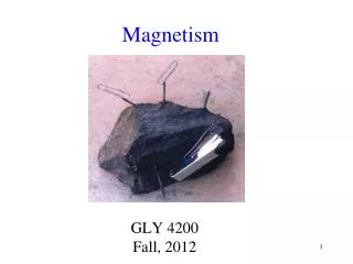
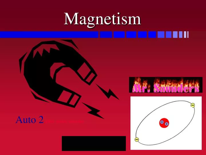
Magnetism Auto 2 after series circuits
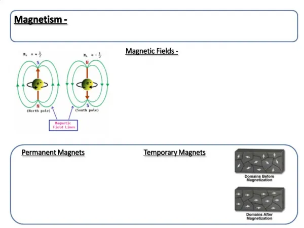
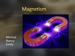
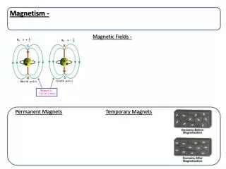
Magnetic flux lines Flux Always flows from North to South
Arrangement of atoms In metal that has not been magnetized
Arrangement of atoms In metal that has been magnetized
Permeability Ability of materials to become magnetized
Reluctance Resistance to magnetic lines of flux High reluctance = Air Low reluctance = Soft Iron
Electromagnetism Any time current flows thru a conductor, A magnetic field is created around the conductor
Electromagnets • Can increase the strength by; • Adding more windings • Increasing the current • More voltage • less resistance • Wrap windings around something with low reluctance
Conventional Theory Says: Current flows From Positive “+” to Negative “-” Left hand thumb rule applies: With left thumb pointing the way current Flows, your fingers show you which Way the magnetic field is built around.
Electron Theory Says: Current flows From Negative “-” To Positive “+” Right hand thumb rule applies: With right thumb pointing the way current Flows, your fingers show you which Way the magnetic field is built around.
Saturation Is the point where the magnetic strength eventually levels off More windings, the longer it takes but the stronger the field
Saturation Shorted coil Two coil ramps Taken with a Lab Scope and An amp probe. Saturation point Turn on point About 4.25 mS Amps = magnetic field Saturation point Turn on point Time in miliseconds
Relays • Use a small amount of current to control (switch) a large amount of current • Control circuit has a winding to create a magnetic field (#1 & #3) • Low amp circuit • Also called the primary • Controlled circuit has a switch to control current flow to a higher amp load (#2 & #4) • Also called the secondary • High amp circuit
Relay in operation 1 & 3 the control circuit Send current Thru 1 & 3 to Create field High current Switched to Load out #2 2 & 4 the controlled circuit Voltage present at #4 Trying to push current Out #2 to high current load
Normally Open (N O) Relay • Takes energy to switch closed • No energy, switch is open • Normally Closed (N C) Relay • Takes energy to switch open • No energy, switch is closed Normally Open and Normally Closed
ISO Mini Relay Most manufactures went to this standard NC NO Terminals #30 to #87a are NC and terminals #30 to #87 NO
Terminals #85 & #86 are the control Circuit (winding) usually 70 ohms ISO Mini Relay Terminal #87 goes to load Controlled circuit Terminal #30 comes from B+ Terminal #87a is rarely used (wiper park circuit)
Find control and controlled Circuits with ohmmeter Power up control circuit While checking controlled Checking Relays
Typical horn circuit In steering wheel
Parallel Circuit Rules • More than one path • Has a splice in the circuit • Voltage stays the same • Total Amperage is divided between the paths • Total Resistance is always lower that the smallest path or branch
OHMS LAW STILL WORKS THE SAME If volts and ohms Are equal, then One amp will flow.
Parallel circuit questions? Lets apply what we Have learned.
Don’t panic! • Apply what you have learned about relays and parallel circuits • Draw up a typical horn circuit • Remember the horn switch is in the steering wheel • We don’t want to send the high current through the horn switch, so we will use a relay • The horn is the load that will use high amps • Make sure there is a complete path in the controlcircuit and the controlled circuit
YOU CAN DO IT! • Apply what you have learned about relays and parallel circuits • Draw up a typical horn circuit • Remember the horn switch is in the steering wheel • We don’t want to send the high current through the horn switch, so we will use a relay • The horn is the load that will use high amps • Make sure there is a complete path in the controlcircuit and the controlled circuit