Download
1 / 25
600 likes | 1.94k Views
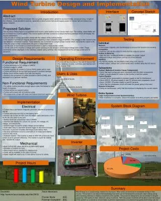
Wind turbine blade design using FEM. Afolabi Akingbe Wei Cheng Wenyu Zhou. Outline. Basics of wind turbine blade Blade element theory Membrane & plate bending model Shell element in FEM ANSYS model. How wind turbine blades work. Essential blade concepts. chord. Twist angle.

E N D
Wind turbine blade design using FEM AfolabiAkingbe Wei Cheng Wenyu Zhou
Outline • Basics of wind turbine blade • Blade element theory • Membrane & plate bending model • Shell element in FEM • ANSYS model
Essential blade concepts chord
Membrane & plate bending • 3D structures under arbitrary loads • Split element into two types for different calculations • Membrane element for in-plane loads • Plate bending elements for transverse loads and bending
Membrane element analysis • Assume linear displacements • are 2x2 matrices
Bending element analysis • Tranverse displacements and rotations are taken as degrees of freedom. • are 4x4 matrices
FEM for shell analysis • A combination of a plate bending and membrane element • The DOF of a plate and plane stress finite element in a local element-aligned coordinate system are considered
Shell element (a) Plane deformation (b) bending deformation The finite element solution
Displacement model • The displacement model for the flat shell is expressed as Ni is the bilinear shape functions associated to node i, and
Strain and curvature • The membrane εm and curvature κare defined as Transverse shear strain is
Approximation of strain field • The membrane deformation, the approximation of the strain field is
Discrete curvature field • The discrete curvature field is
Approximation of shear strain • The approximation of shear strain is written as
Linear system • Combining simultaneously membrane and bending actions, a linear system for the vector of nodal unknowns q can be written where ke is the stiffness matrix composed of membrane and plate stiffness element matrices
Load vector • The load vector at each node i is of the form fie = [FxiFyiFziMxiMyiMzi]T
Element stiffness matrix • The element stiffness matrix at each node i
ANSYS Modeling • Angular velocity • Surface pressure
Deformation & stress contours • More stress at the blade root • Thicker material closer to root to endure high loads (Displacement contour) (Stress contour)
Composite • Can use commercial code like ANSYS to quickly change material properties and mesh sizing.